If you care to patch a version with the spaghetti jumps to test what correcting this does, I'll be happy to test it out. The potential of fixing the single cycle DMA clicking is even more appealing to me than the hanging notes.
You can test it ))
But I wouldn't have high hopes for this patch. Better to hack 4.16 ))
what's to say that 4.16 would even run on the earlier hardware? since they had integrated DSP by then there could have been all kinds of GPIO changes
It may be uncompatible, but it is good base for differential analysis.
But, knowing the level of competence of the developers, I wouldn’t be surprised if this is just 4.13 patched in several places.
They simply aren't able to make massive changes to the code to keep it stable.
BTW, found other bug in Timer0 interrupt handler - they dont store/restore R0, but they used it in one path of handler execution.
So - Every interrupt handler is flawed. If ANY interrupt is triggered, command execution can be wrong.
If no one else has a socketed AWE32, I've got a CT2760 I can socket the 8051 on and try the patched code for NMI compatibility. Will be a couple weeks before I get around to pulling that system on to the bench though.
I have 5 different AWE32's, CT2760 Rev1 ,Rev3, 3900, 3980, and 3990 w/ASP. What is the socket that is needed?
PLCC-44 for surface mount, i.e. SMD type and not with pins underneath.
Also, the bottom plastic needs to be easy to remove (otherwise you cannot solder it by hand), which is kind of hard to judge by the picture of the socket itself - I am making this note, because after using cheap non-branded PLCC sockets, I decided to go expensive and fancy with "3M" branded made one - it was build like a tank - very hard to remove the bottom, because of very hard high-quality plastic - even using very sharp cutting pliers managed to damage some of the metal contacts, because so much force needed to be applied to cut through such hard plastic.
last, but not least here is a good video how to solder by hand PLCC socket with removing the bottom:
After prepping the PLCCs, where would it go on the AWE32 for example?
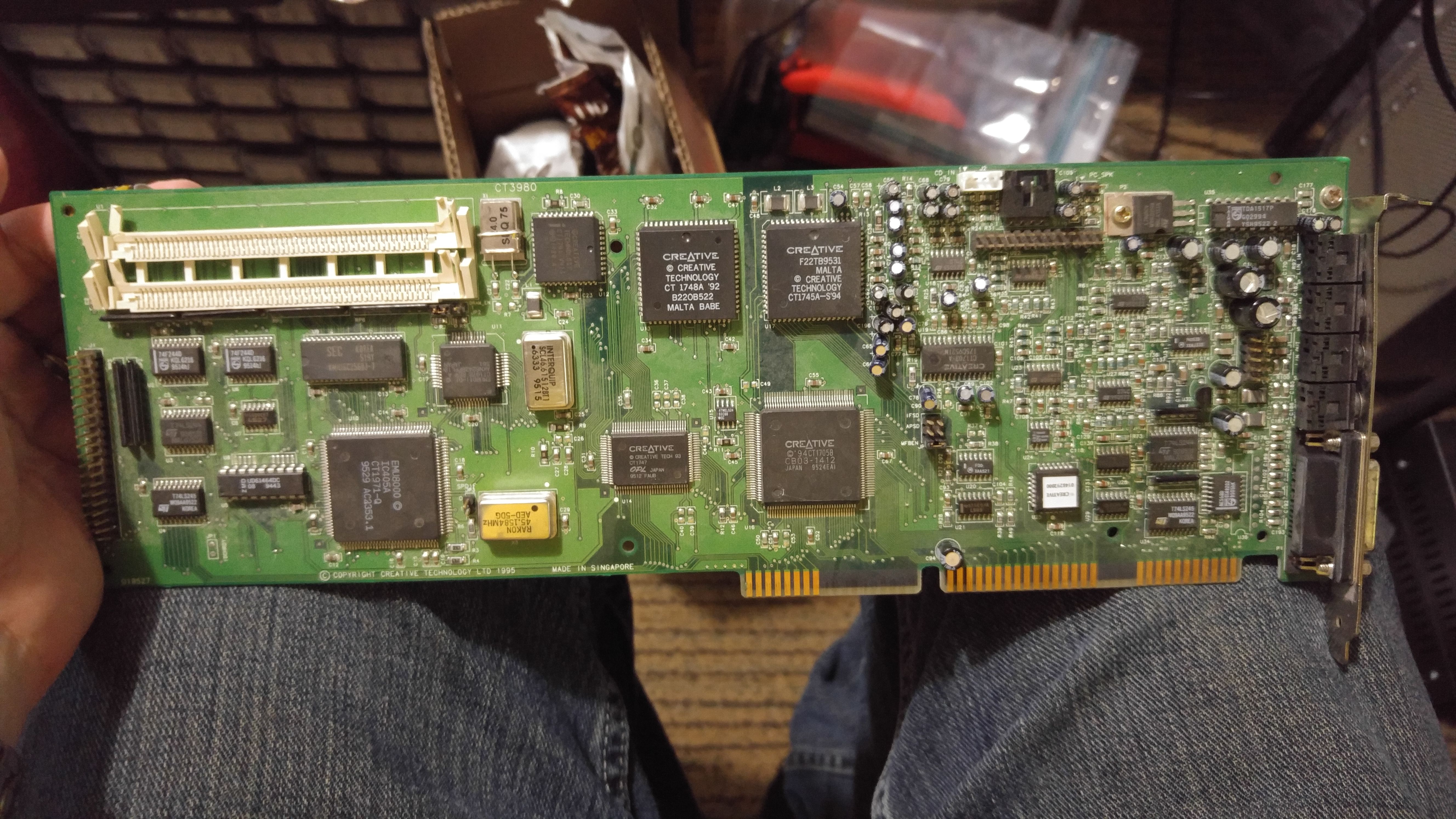
I presume the DSP chip is on different location on the PCB depending on the exact AWE32 model and thus I cannot speak for all models, but on mine CT2760 it's the following chip - CT1741 - it's also the only PLCC-44 packaged chip on the PCB and thus easy to locate just by that:
as you can see even the exact version "V4.12" is written on the chip. So, in my case will be double upgrade - not only to V4.13, but to bug-fixed V4.13 (big thanks to @Maelgrum). So, the steps are:
1. de-solder the original chip
2. install PLCC-44 socket
3. use external programmer to program new replacement chip with what is posted here
4. install that new chip from step 3.
And I have one questions myself for step 3 : do only AT89S52 and AT89C52 tested and confirmed as working for a replacement chip?
PLCC-44 for surface mount, i.e. SMD type and not with pins underneath.
Also, the bottom plastic needs to be easy to remove (otherwise you cannot solder it by hand), which is kind of hard to judge by the picture of the socket itself - I am making this note, because after using cheap non-branded PLCC sockets, I decided to go expensive and fancy with "3M" branded made one - it was build like a tank - very hard to remove the bottom, because of very hard high-quality plastic - even using very sharp cutting pliers managed to damage some of the metal contacts, because so much force needed to be applied to cut through such hard plastic.
last, but not least here is a good video how to solder by hand PLCC socket with removing the bottom:
I agree, it's needed to lift the chip to the correct level - after I cut it and solder the socket, i put it back - it stays between the PCB and the chip - that works for me. However, I will try your advice to use curved tip as well.
BTW, I see the original Creative chip is made by "SIGNETICS" - that is the big "S" logo on my picture from my previous post. I wonder what SIGNETICS generic chip is the closest replacement instead use Atmel.
S95Sedanwrote on 2023-09-26, 21:39:Is this suppose to fix the Single-cycle DMA clicking? Or something else?
Clicking is the same in duke2. […] Show full quote
PLCC-44 for surface mount, i.e. SMD type and not with pins underneath.
Also, the bottom plastic needs to be easy to remove (otherwise you cannot solder it by hand), which is kind of hard to judge by the picture of the socket itself - I am making this note, because after using cheap non-branded PLCC sockets, I decided to go expensive and fancy with "3M" branded made one - it was build like a tank - very hard to remove the bottom, because of very hard high-quality plastic - even using very sharp cutting pliers managed to damage some of the metal contacts, because so much force needed to be applied to cut through such hard plastic.
last, but not least here is a good video how to solder by hand PLCC socket with removing the bottom:
I agree, it's needed to lift the chip to the correct level - after I cut it and solder the socket, i put it back - it stays between the PCB and the chip - that works for me. However, I will try your advice to use curved tip as well.
BTW, I see the original Creative chip is made by "SIGNETICS" - that is the big "S" logo on my picture from my previous post. I wonder what SIGNETICS generic chip is the closest replacement instead use Atmel.
Helps to have a microscope though, otherwise you might easily reflow it using chipquick or something so the socket doesn't melt.
Creative used a couple vendors themselves, intel, signetics, mhs.
I used to refuse to cut the bottom, and yes it's possible to solder it that way, but eventually I just started cutting it because it makes the whole process much faster and there is a little hole in the PCB you can use to push the chip out after. I've had zero problems resulting from the chip being inserted "in too deep". Socket is made by mill-max from digikey
Last edited by maxtherabbit on 2023-09-26, 23:38. Edited 1 time in total.
Creative used a couple vendors themselves, intel, signetics, mhs.
I see, I am asking for Signetics, not so much because the original Creative chip on my AWE32 board is made by them, but because they were acquired by Philips and in Europe new-old-stock of Signetics chips are usually very easy to find and very cheap - even saves you the hassle dealing with fake Chinese parts. last time Signetics 27C512 part was like 5 times cheaper for me to get than corresponding Atmel part. Anyway, my best guess is that it's "Signetics SC87C51" - because that is the only Signetics chip I managed to find with "(C) INTEL 1980" on it.