VOGONS


First post, by ElBrunzy

User metadata
Rank Oldbie
Rank
Oldbie

Hi,

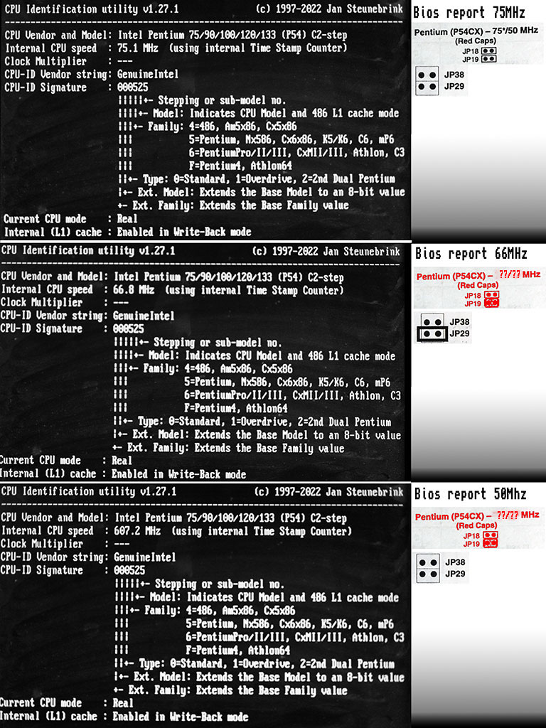
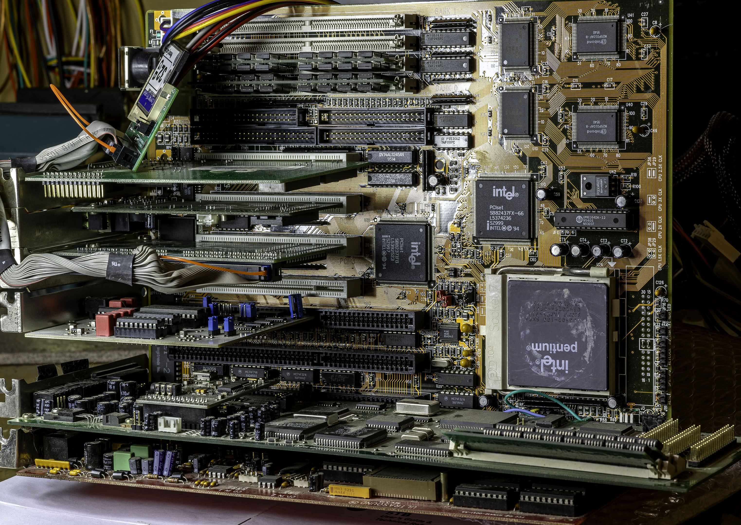
I'm very glad to present you my newest project. I have a socket 7 P55C pentium 1 MMX motherboard that recently fried. I'm so thankful that it brough none of it's attached cards with it. I bought a Soyo motherboard to replace it, not realizing that it would only support P54C? CPU. Luckily I had one sx963 CPU carelessly stored in back of my processor drawer. After a meticulous pin redressing process, and some help from PC@LIVE, I could boot that motherboard and proceed to setup that CPU. Of course I could not help myself but to try undocumented setup here in red. To my surprise it would run the CPU at 50mhz.

soyo_5tb_undocumented_config_50_50.jpg

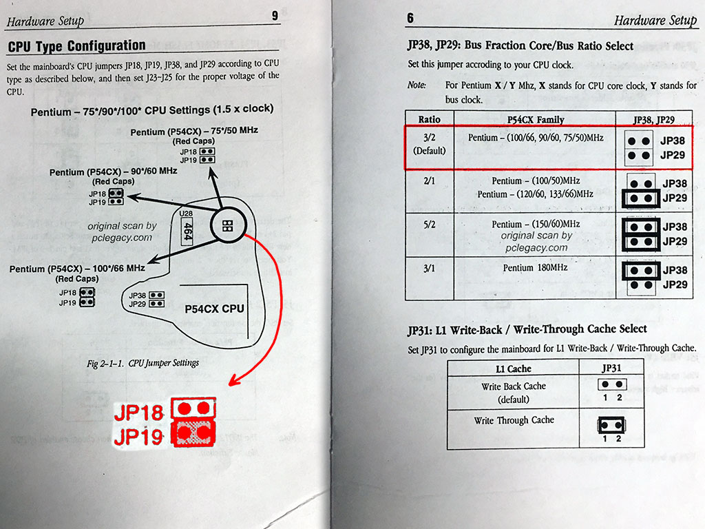
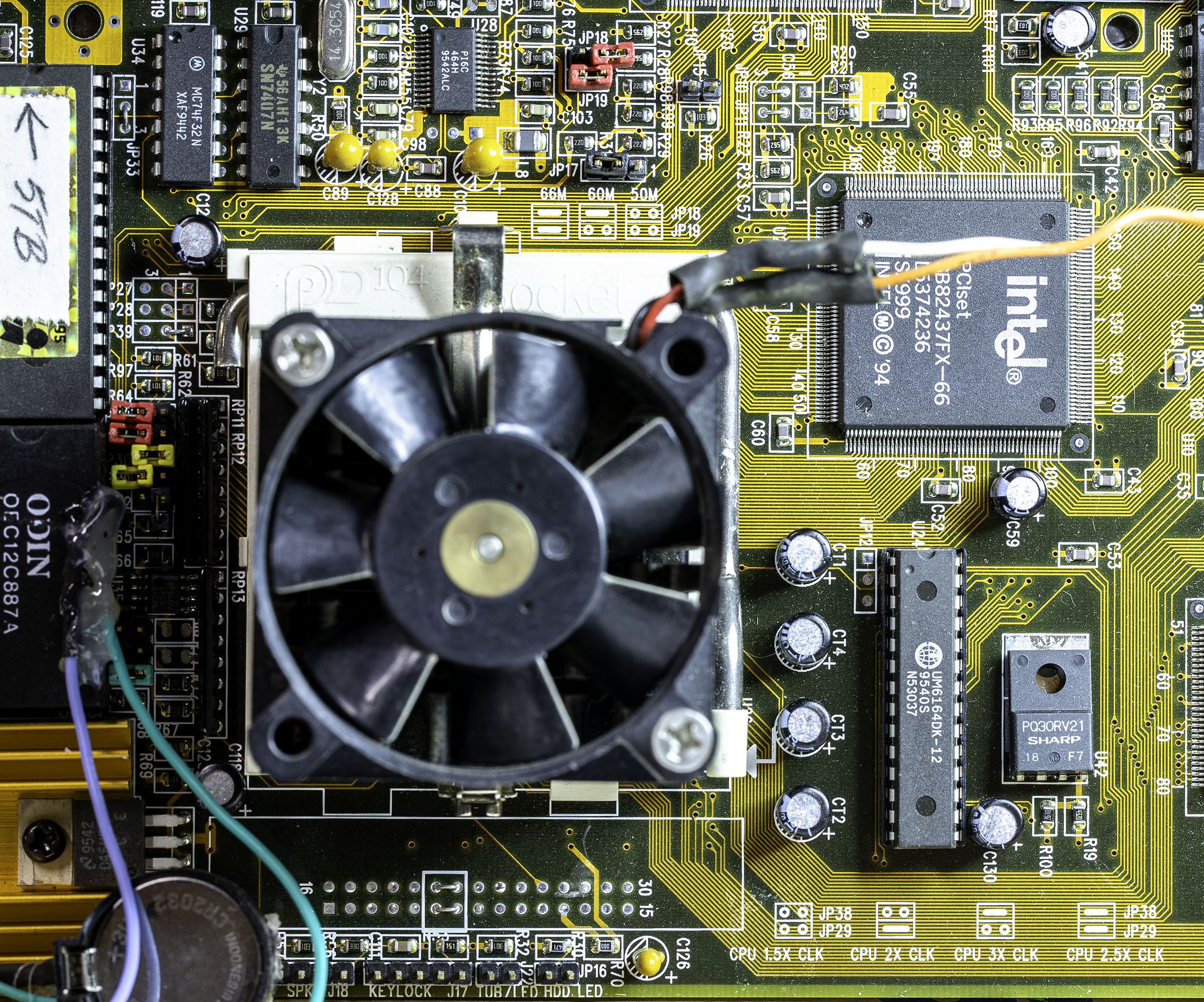
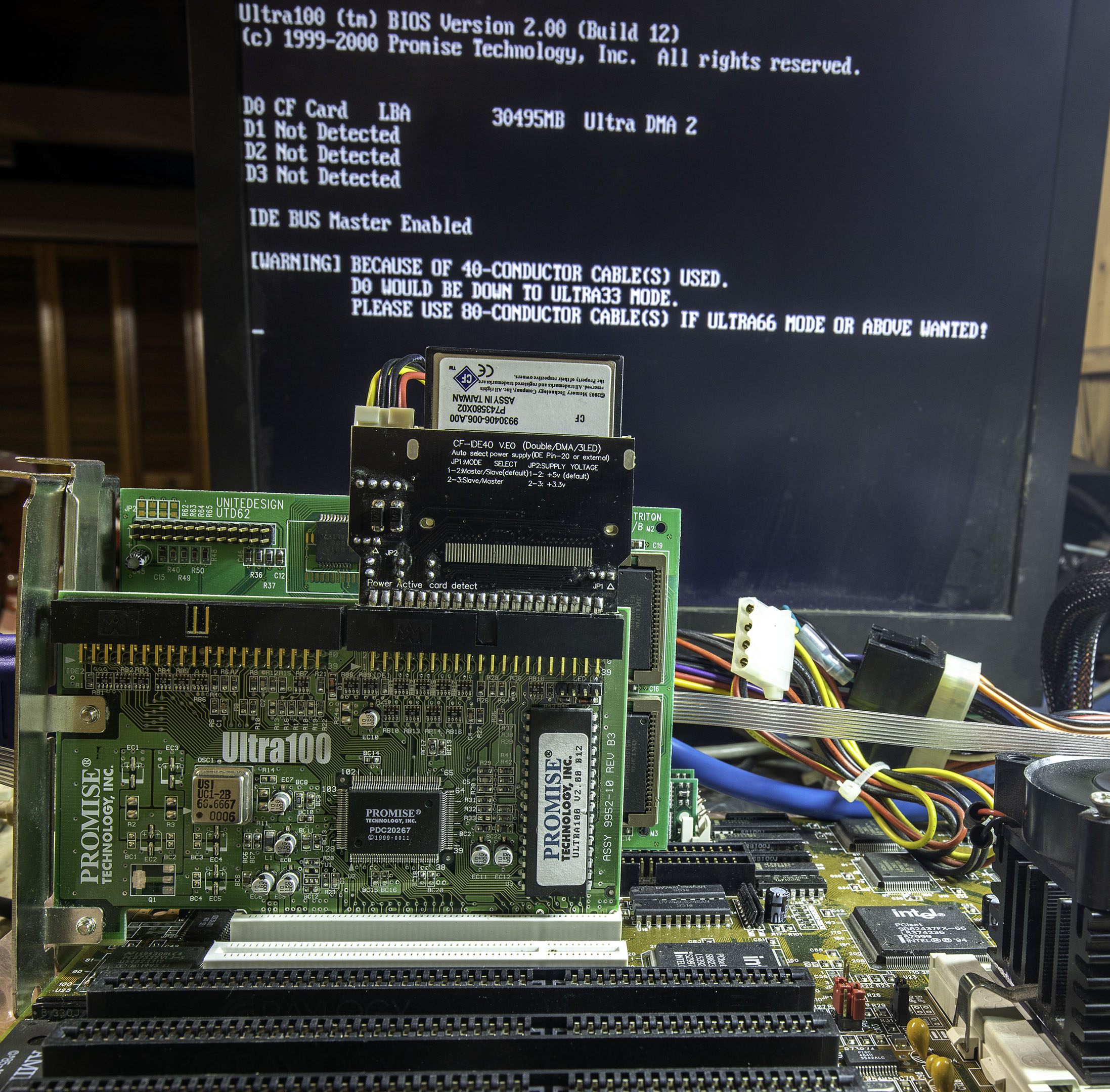
I'm not sure I understand excatly how the J38 and J29 jumpers and ratio configuration are related so maybe they setup a configuration written elsewhere. Here on page 9 we learn that 3/2 Ratio is 1.5x clock, on page 10 and 11 they say ratio 2/1 and 5/2 would be 2.0x and 2.5x respectively. There is no information about 3/1, which I guess would be related to a Pentium 180MHz with secret bus speed. I remember reading on vogons someone talking about 1.0x clock and how it was or was not supported by the CPU configuration. While 50MHz is ideal for me because I mainly load music player or watch 1990~95 demos on that, and CPU run so cool that the silent 5v fan dissipating the heatsink could even break I would not be too worried. But I wonder if it's not undocumented for a reason. The Promise Ultra133 PCI IDE drive would crash the BIOS PNP Init detection (it would work at any other documented valid CPU and Bus configuration). I also have an Ultra100 version of that card that work just fine and then every other expansion card would work and could be tested on that board.

soyo_5tb_p54c_gus_awe32_saaym.jpg

There is also an option about AT Bus Clock Select between devided by 3 or by 4. Since ISA soundcards is the main interest here I was wondering what would be the safest option. I remember having trouble running inertia player because the recovery time was too high and I'm afraid it might be similar.

Some people on that forum have been able to bring down those P5/P54Cx to rather impressive crawl. But there is a point where a retro computer dont represent what your rich uncle had in 90~95. A visit to the BIOS to disable CPU caches usually take care of the rare case when ridiculous stroll is needed. But before I close that case I am wondering if I should let the JP31 L1, I have searched the forum about it and the difference seem insigificant most of the time. Scali did a very nice job at the end of this thread explaining it.

Reply 1 of 16, by konc

User metadata
Rank l33t
Rank
l33t

The manual lists settings in a weird way I'm not used to, but my understanding is that
JP18-19 control the CPU bus speed (50, 60, 66MHZ)
JP39-29 control the multiplier (x1.5, 2, 2.5, 3)
Does this make any sense? If so the undocumented setting should be 33MHz.

Reply 2 of 16, by Bruno128

User metadata
Rank Member
Rank
Member

What does CHKCPU by J. Steunebrink tell?

IDE ctrl card instability can mean PCI clocked higher than 33mhz. You chose a divider of 3/2 meaning you would ideally want 50mhz bus.

SBEMU compatibility reports list | Navigation thread

Reply 3 of 16, by Sphere478

User metadata
Rank l33t++
Rank
l33t++

It’s probably running at 50mhz bus, 75 mhz core

Sphere's PCB projects.
-
Sphere’s socket 5/7 cpu collection.
-
SUCCESSFUL K6-2+ to K6-3+ Full Cache Enable Mod
-
Tyan S1564S to S1564D single to dual processor conversion (also s1563 and s1562)

Reply 4 of 16, by ElBrunzy

User metadata
Rank Oldbie
Rank
Oldbie

With the suggestion of Bruno128 (hey we have the same given name, I will go register Bruno256 right away!) I ran some test with cpuchk.exe and the result at 50mhz really tell me it is a bad idea to run that cpu at this configuration. Even at 66MHz it appear more consistent yet the ultra133 card only wanting to show up at 75MHz give me the impression I should set it there and call it a day to avoid any further complication.

p54c_sx963_cpuchk.jpg

I agree with what you say konc and we can confirm that if we set the multiplier at 2 then the CPU spin at 66MHz. But the CPU would not work at 83MHz 😔 oh well, what do we care anyway ? Your theory is confirmed to me already and it's over 75MHz that seem stable and valid.

I was able to corrupt my cf card running win98 with the promise Ultra100 with a CPU in an invalid configuration giving me the impression it's not a good idea. Now that I notice, the Ultra100 has it's own crystal oscillator at 66MHz while the Ultra133 dont but has more pin on the PCI connector, so I guess it is dependent of it's host clock and might be why it's not working on that motherboard. Hopefully testdisk will save the day now, once again...

Edit : just to note that CPUCHK.EXE /I give good reading of the 50Mhz setting, I read about that switch afterward

Reply 5 of 16, by Bruno128

User metadata
Rank Member
Rank
Member
ElBrunzy wrote on 2024-11-15, 23:58:

But the CPU would not work at 83MHz

83MHz bus is mostly found on super socket 7 chipsets like VIA. On Intel you then have PCI at 41.5MHz which is too much for many cards. The one exception I know is ALi Aladdin IV+ chipset that would have a divider for that frequency providing 33MHz PCI nevertheless.

SBEMU compatibility reports list | Navigation thread

Reply 6 of 16, by H3nrik V!

User metadata
Rank Oldbie
Rank
Oldbie

Don't get it ... it's the FSB jumpers, that give you the 50 MHz CPU speed rather than the multiplier jumpers? It smells too me like it actually runs at 33 MHz FSB? Does the P54C even know of lower than 1.5 multiplier, I mean, slowest spec is 75 ie 50 x 1.5.
AFAIK, only P5 and Overdrives can do 1x the latter as a fault-safe in case the fan fails.

If it's dual it's kind of cool ... 😎

--- GA586DX --- P2B-DS --- BP6 ---

Please use the "quote" option if asking questions to what I write - it will really up the chances of me noticing 😀

Reply 7 of 16, by Sphere478

User metadata
Rank l33t++
Rank
l33t++

Something isn’t right here. Try a different program. Like a memtest floppy or something.

Sphere's PCB projects.
-
Sphere’s socket 5/7 cpu collection.
-
SUCCESSFUL K6-2+ to K6-3+ Full Cache Enable Mod
-
Tyan S1564S to S1564D single to dual processor conversion (also s1563 and s1562)

Reply 8 of 16, by ElBrunzy

User metadata
Rank Oldbie
Rank
Oldbie

Sphere478, Memtest86 v3.7 reported the correct CPU speed, even at 50MHz.

H3nrik V!, I think my screenshot might have added to the confusion, I copied the 90/60MHz image section and just rotated 180' the jumper to give the impression of the undocumented only JP19 shorted setting but forgot to remove the 90/60MHz text, I replaced it with ??/?? now. I remember someone on another thread told something like frequency table where into the CPU and setup via some pin connection, maybe that's why it's so hard to figure a logic out of those jumper configuration. I think having JP19 only jumped maybe set the bus clock to undocumented 33MHz. I found the silkscreen more clear than the manual, In the picture, at the left of the CPU we can see red opened JP39 and JP29 set to 1.5 with the documentation on the lower-right of the CPU. On top of the CPU picture, you can read JP18 and JP19 silkscreen documentation and the red jumper over it is set at what our investigation lead us to believe would be 33MHz.

p54c_sx963_soyo_silkscreen.jpg

Even with standard documented valid configuration that computer end up being unstable and very prone to crash. So I proceeded to do some testing at undocumented and documented settings, the result where the same : Memtestx86 would run for about 14hours without error and msdos Scandisk would scan entire 32gb CF card without a hiccup. But Win98SE would keep on crashing, booting in Registry fix loop or even corrupting the entire CF card !

So apparently that CPU seem stable at 50MHz and the problem narrow down to that PCI IDE controller. I think the Ultra66/100 implementation might not work well with that card. So, using an adapter that limit it to Ultra33 seem to fix what caused issues in Win98SE.

Before I realized the PCI IDE would probably be the issue, I experimented with WFW3.11 on DOS7.10, once patched it worked surprisingly well, but the lack of LFN made it quite a tedious task to copy large group of file as it halt so often for being very pedantic about the 8.3 standard.

With the PCI IDE Set to Ultra33 win98 install went roundly and so far everything seem stable. I could install driver for the CL5446, DFE538TX and Promise Ultra100. The onboard IDE controller was nice enough to use no IRQ while it could not be totally disabled. So now it's on for another night of hard disk scanning on Windows and hopefully tomorrow I wont wake up to a crashed computer, finger crossed !

promise_ultra100_cf32gb_udma2.jpg

Last edited by ElBrunzy on 2024-11-18, 03:48. Edited 1 time in total.

Reply 9 of 16, by Disruptor

User metadata
Rank Oldbie
Rank
Oldbie
ElBrunzy wrote on 2024-11-15, 23:58:
With the suggestion of Bruno128 (hey we have the same given name, I will go register Bruno256 right away!) I ran some test with […]
Show full quote

With the suggestion of Bruno128 (hey we have the same given name, I will go register Bruno256 right away!) I ran some test with cpuchk.exe and the result at 50mhz really tell me it is a bad idea to run that cpu at this configuration. Even at 66MHz it appear more consistent yet the ultra133 card only wanting to show up at 75MHz give me the impression I should set it there and call it a day to avoid any further complication.

p54c_sx963_cpuchk.jpg

I agree with what you say konc and we can confirm that if we set the multiplier at 2 then the CPU spin at 66MHz. But the CPU would not work at 83MHz 😔 oh well, what do we care anyway ? Your theory is confirmed to me already and it's over 75MHz that seem stable and valid.

I was able to corrupt my cf card running win98 with the promise Ultra100 with a CPU in an invalid configuration giving me the impression it's not a good idea. Now that I notice, the Ultra100 has it's own crystal oscillator at 66MHz while the Ultra133 dont but has more pin on the PCI connector, so I guess it is dependent of it's host clock and might be why it's not working on that motherboard. Hopefully testdisk will save the day now, once again...

Edit : just to note that CPUCHK.EXE /I give good reading of the 50Mhz setting, I read about that switch afterward

Your BIOS reports are correct.

BIOS 75 = FSB 50 x 1,5 & PCI 25
BIOS 66 = FSB 33 x 2 & PCI 16,6
BIOS 50 = FSB 33 x 1,5 & PCI 16,6

Several PCI cards don't really like to be operated with 16 MHz PCICLK.

Reply 10 of 16, by Sphere478

User metadata
Rank l33t++
Rank
l33t++

Oh okay.

Yes, after seeing that pic of your mobo I do believe you did indeed find a 33x1.5 setting.

Cool!

Sphere's PCB projects.
-
Sphere’s socket 5/7 cpu collection.
-
SUCCESSFUL K6-2+ to K6-3+ Full Cache Enable Mod
-
Tyan S1564S to S1564D single to dual processor conversion (also s1563 and s1562)

Reply 11 of 16, by mkarcher

User metadata
Rank l33t
Rank
l33t

The clock chip on that board has this datasheet: https://www.jameco.com/Jameco/Products/ProdDS/2302583.pdf - it seems like the S0 input is forced low, and S1 and S2 are set by the jumpers.

Reply 12 of 16, by ElBrunzy

User metadata
Rank Oldbie
Rank
Oldbie

Amazing, I learn so much by posting in that forum with everyone help and I'm very grateful about it. I don't think I would ever figure out about that PI6C464 chip. So now I could either close that computer and be happy with a Pentium 1 running at 50MHz or try to short S0 and try to make it run at 45MHz or 38MHz. The gain is pretty low and the risk is to fry a computer that seem perfectly fine by now (because it completed the latest test). The two adjacent pins being S1 and AGND I think the consequences of a short should not be dramatic as this chip is rather small. Although in case of a success I wonder if that CPU would run at those speed... there is only one way to find out, but there is no hurry, better think about it for a bit.

Reply 13 of 16, by H3nrik V!

User metadata
Rank Oldbie
Rank
Oldbie
ElBrunzy wrote on 2024-11-18, 04:18:

Amazing, I learn so much by posting in that forum with everyone help and I'm very grateful about it. I don't think I would ever figure out about that PI6C464 chip. So now I could either close that computer and be happy with a Pentium 1 running at 50MHz or try to short S0 and try to make it run at 45MHz or 38MHz. The gain is pretty low and the risk is to fry a computer that seem perfectly fine by now (because it completed the latest test). The two adjacent pins being S1 and AGND I think the consequences of a short should not be dramatic as this chip is rather small. Although in case of a success I wonder if that CPU would run at those speed... there is only one way to find out, but there is no hurry, better think about it for a bit.

Depends if S0 is pulled down via a resistor or hard shorted to ground. If the latter, you'll be shorting supplies, if you just short S0 to a positive supply. In that case, you'll need to unsolder the pin from the motherboard to pull it high (preferably through a resistor rather than just a short).

[Edit] the data sheet specifies tha S0 through S2 have internal pull-ups, so it should be enough to just lift the pin from the motherboard (depending on what your solder skills are)

If it's dual it's kind of cool ... 😎

--- GA586DX --- P2B-DS --- BP6 ---

Please use the "quote" option if asking questions to what I write - it will really up the chances of me noticing 😀

Reply 14 of 16, by ElBrunzy

User metadata
Rank Oldbie
Rank
Oldbie

I'm not sure about my soldering skill but I think my patience and luck allowed me to successfully lift the 11th pin from. I'm not sure a rollback is possible although I think I could solder the pin to a ground via a jumper wire if ever needs be. It took me time to find a working configuration which was very taxing on my nerves but I was very happy to find a working 33MHz configuration, which was unexpected, but better than anticipated. At this point I'm not even sure a heatsink is necessary, but why not ?

p54c_pi6c464h_pin11_s0_lift.jpg

I dont understand what is going exactly right now, on so in the meantime I'll just note the working configuration and their frequency given :

JP18;[..],[--],[..],[--] (S2)
JP19;[..],[..],[--],[--] (S1)
3/2 : 33, 40, 60, 120
2/1 : 50, ~~~, 75, !!!
5/2 : 100, !!!, !!!, !!!
3/1 : 75, !!!, !!!, !!!

~~~ = dont boot (CPU heat in a controlled way but never POST)
!!! = CPU become too hot quickly and must be closed before it finish the POST
[--] = jumper on
[..] = no jumper

To me it appear silly that this S0 pin was pulled up as it seem there is more configuration available with it lifted. Of course this configuration table belong to that sx963 CPU, I understand that more configuration mean more support cost and today trend to slow down a computer to target a retro period is against the motherboard contemporary trend that was to push performances.

I would like to pursue the thread conversation but I consider my quest for the ideal speed for that computer achieved. 33MHz is a very nice speed for a retro computer targeted at listening to music on hardware soundcard, at that speed I think I can leave the CPU fan off and that 30cm socket 7 heatsink would suffice. Also I have not put back other expansion card than the video card on the motherboard so maybe it's too soon to cry victory !

Reply 15 of 16, by H3nrik V!

User metadata
Rank Oldbie
Rank
Oldbie

Wonder if the PCI clock is directly from the MCLK1 output of the clock generator ...

If it's dual it's kind of cool ... 😎

--- GA586DX --- P2B-DS --- BP6 ---

Please use the "quote" option if asking questions to what I write - it will really up the chances of me noticing 😀

Reply 16 of 16, by ElBrunzy

User metadata
Rank Oldbie
Rank
Oldbie

For what it worth, I could not test a direct continuity between pin B16 of a PCI slot and pin 24 or 25 of the PI6C464.

cheers !

EDIT : well, that was confusing. What I meant is I did test continuity between B16 and pin 24 or 25 but there was none. So my guess is that maybe the multiplier jumper interface the clock via another chip. I have no motivation in figuring it out as now the computer setup is ideal to me and I am in the process of closing it back together. I felt compelled to test it to express my gratitude toward your help and in the general interest of the PCI bus clock.