VOGONS


What retro activity did you get up to today?

Topic actions

Reply 31000 of 31005, by MattRocks

User metadata
Rank Member
Rank
Member
giantenemycat wrote on 2026-03-22, 21:18:
Have set up two contenders for my alternate-timeline-2006-second-hand-cheapo-PC. […]
Show full quote

Have set up two contenders for my alternate-timeline-2006-second-hand-cheapo-PC.

The attachment dubious.jpg is no longer available

The MESH has an ASUS A7V-E - Socket A (VIA KT133). Athlon 1100, 256MB SDRAM.

On the right in that lovely tacky case, we have a Gigabyte GA-8SIMLH - Socket 478 (SiS 651). Pentium 4 2.0 (Northwood), 512MB DDR (in single-channel for the jank).

Which would you pick?

I'd put the AMD in the blue case 😉

Reply 31001 of 31005, by DaveDDS

User metadata
Rank Oldbie
Rank
Oldbie

Looked through my boxes of IC tubes, for a 6264 (8k SRAM), lots of 62256s (32k) but no 6264s! Then I "remembered" the "long forgotten" boxes of ICs in a back corned of my workshop and went through then... found 5 6264s (yay!) but also a some other pretty interesting old ICs:

Several 2016 (2k SRAM) and 5516 (2k CMOS SRAM)

2x 486 CPUs - I didn't think I had any x86 prior to Pentium anymore!

3x 8080, 2x 8085, and 2x Z80 CPUs

4x 68000 CPUs (original 64pin DIPs)

1x 1702 EPROM (256byte) I knew I still had a few 2708s (1k) but I've not seen a 1702 in years (this is the first EPROM type I ever worked with!)

1x 1771 floppy disk controller (very early - might be the 1st WD)

Lots more "old stuff" but these were the ones which stood out to me.

Dave ::: https://dunfield.themindfactory.com ::: "Daves Old Computers"->Personal

Reply 31002 of 31005, by giantenemycat

User metadata
Rank Newbie
Rank
Newbie
MattRocks wrote on Today, 00:36:

I'd put the AMD in the blue case 😉

I thought of that, but I would feel weird gutting the MESH. I got it from a very nice man with a very nice Philips 107E CRT for a very nice price.

This manual he still had is the main reason I don't wanna mess with it, gotta preserve that slice of history. Windows ME and hard drive issues...sounds about right. Come to think of it, that probably explains why there's a 120GB HDD in there. That would have been crazy for 2001.

Reply 31003 of 31005, by Ozzuneoj

User metadata
Rank l33t
Rank
l33t
Ozzuneoj wrote on Yesterday, 23:43:
Whelp... I had already reassembled the GRID system when I got the idea to make my own SIPPs, so I ended up being a bit off with […]
Show full quote
Ozzuneoj wrote on 2026-03-21, 20:14:
Yeah the SIPP sockets are very cramped in this system. […]
Show full quote
BitWrangler wrote on 2026-03-21, 12:02:

I think custom is gonna be the way then, all the SIPPs I have come across are more like 15-20mm, so shorter ones must be super rare, but I've seen ~10mm high SIMM. There are angled SIMM slots though, but if you haven't got horizontal clearance those will be out too.

For games, if you've got an inverse function key or button, that makes things easier, I have seen some that let you cycle the colors/greyscales. Maybe also there is a TSR for that. The Wolfenstein3D CGA mod will probably run nice on current RAM. FastDoom has gained CGA modes, but needs 4MB. Other stuff, there was some 1987ish to 1990ish games that came out with CGA but then in budget rereleases 90-93 only had VGA. Some stuff I can think of in CGA is StarGoose, Outrun, Elite, Prince of Persia... there's also that big thread on here about CGA games on Mono. But yeah, apart from FastDoom, I can't think of anything that demands more than 1MB. I don't suppose you noticed the video chip when you were last in there? If it's a paradise or something you might get more than plain CGA out of it, not that you'll notice too much benefit, but there's maybe a game or two that had a mode between CGA and VGA.

edit: thread Best CGA & Hercules monochrome games

Yeah the SIPP sockets are very cramped in this system.

The attachment rams (1).jpg is no longer available
The attachment rams (2).jpg is no longer available
The attachment rams (3).jpg is no longer available

I have a decent assortment of very small 1MB SIMMs, so I'm hoping I can use some of these.

The attachment rams (4).jpg is no longer available

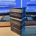
The ones on the right are around 12.7mm tall, but given the CPU and video limitations I really don't think 8MB would provide much more functionality than 4MB, and I would prefer not to break up a matching set of 8. So I am leaning toward using this set of 4, which are around 14.5mm tall.

The attachment rams (5).jpg is no longer available

These IBM branded memory chips seem uncommon and I cant find a datasheet for them but according to this page these should be 1MB sticks. Of course I will have to install them to find out if they are compatible, but don't think it will be too hard to solder some pins to them. I will try to figure out beforehand if I actually have an extra 2mm of space in there... but I might be able to install four sticks at a slight angle even if they are a bit too tall.

I am looking forward to this though. I don't know why, but having a system upgraded to the point that it is as balanced and as useful as it realistically could be makes it seem "complete" and gives me a good feeling. Even if it works okay with 1MB and no 387, having 4MB and a 387 installed just feels right.

As for the video chip, it is visible in the first picture above. It is a Yamaha V6366C-J, similar to the one here. It is apparently MDA, Hercules and CGA compatible. I didn't look into it too much, but Checkit said that the system has 16KB of video memory available, so it seems limited to CGA.

The biggest limiting factor in the system I think will be the tiny hard drive. I think I have around 18MB free right now with hardly anything on it. That doesn't leave a lot of room for activities. For me, part of this computer's charm is that it is still running what is likely its original hard drive from 37 years ago, and it sounds cool... Of course, it would be nice to have a CF card or something in there to give more space, performance and reliability. For all I know this drive could be riddled with bad sectors or have other problems... I just haven't used it enough to know.

Interestingly, in the years since I got this machine back in 2020 a TON of work has been done by others to overcome several limitations. At the time there was no reliable way to use a CF card with them due to some BIOS bugs, but this guy seems to have figured out a way to patch the bugs relatively easily. I will consider doing this at some point and switching to a CF card. The rabbit hole is getting deep quickly though. All this started with me just digging this thing out of storage to show to my daughter a few days ago... 🤣

Whelp... I had already reassembled the GRID system when I got the idea to make my own SIPPs, so I ended up being a bit off with the size of the SIMM. These ones are definitely too big. They are too tall once assembled. And it looks like all SIMMs are too wide since they are meant to snap into SIMM slots and this system has only a few millimeters of space on either side of the SIPPs.

The attachment 20260323_193547 (Custom).jpg is no longer available

The two top ones are my attempts to convert SIMMs to SIPPs. I think these would work totally fine for a larger board, so I'll keep them.

The middle one is the original 256K SIPP from the GRIDcase 1530.

The next one down looks like it has no traces in the empty space at the sides, so should be able to be cut down to the size of the tiny SIPP. By comparison, the one under it also doesn't have much there but it looks like there is at least a copper layer in there, where the other one seems to have nothing.

What do you guys think? Could I just cut the ends of that SIMM (4th one down) to be the size of the SIPP without it causing an issue?

EDIT: Doh... I just tested them for fitment and these pins don't even slot into the ones in the GRID motherboard. They are close, but the pins on the old SIPPs are even smaller diameter than these precise round header pins apparently. That really stinks. I don't know of anything else that would work, aside from sanding these ones down, which would be tedious to say the least.

I wonder if I could just swap out the memory chips themselves? I have a big bag of 72pin SIMMs that don't have matches, so one or two of those would likely be good donors.

... the rabbit hole is getting very deep now.

Yes!!

This ended up being the easiest solution. After practicing pulling SOJ chips off of a 72pin SIMM and reattaching some it seemed like something I could do without destroying anything. So I pulled all 8 chips off of the SIMM, pulled the chips off of each SIPP and swapped them out. All I used was a bit of thinned out flux, long angled tweezers, a heat gun and a tiny bit of solder paste for the legs that didn't want to flow with the existing solder (applied as needed with a super tiny flat blade screw driver).

I figured this method would be the safest and least likely to cause any damage to the PCB or solder pads since I am not that great with desoldering braid and don't have much experience using solder paste on multi-leg chips (yet). I think I made the right choice since I had basically no problems at all.

The attachment 1530_1MB (2).jpg is no longer available

After completing each stick I tested every pin with my DMM and everything was connected.

The attachment 1530_1MB (3).jpg is no longer available

I inserted the four SIPPs and the system booted right up and immediately found 4MB of RAM!

The attachment 1530_1MB (1).jpg is no longer available

I'm so happy this worked! This thing is one step closer to being as good as it really ever needs to be.

I have had a bit of trouble getting a patched ROM working properly (to fix BIOS issues related to fast hard drives or CF cards), but I will take another stab at that tomorrow. Once I have that working I'll swap the hard drive for a 512MB CF card. Then I should be able to load this thing up with just about any game or program that uses CGA or monochrome graphics. Should be a fantastic machine for that. 😀

For historical preservation the original memory chips, BIOS ROMs and hard drive will be safely stored in a labeled box... because I can't really imagine doing this any other way. @_@

Now for some blitting from the back buffer.

Reply 31004 of 31005, by rasz_pl

User metadata
Rank l33t
Rank
l33t
Ozzuneoj wrote on Yesterday, 23:43:

What do you guys think? Could I just cut the ends of that SIMM (4th one down) to be the size of the SIPP without it causing an issue?

deffo

Ozzuneoj wrote on Yesterday, 23:43:

EDIT: Doh... I just tested them for fitment and these pins don't even slot into the ones in the GRID motherboard. They are close, but the pins on the old SIPPs are even smaller diameter than these precise round header pins apparently.

I have some vague memory of Feipoa talking about different thickness of machined pins in Custom interposer module for TI486SXL2-66 PGA168 to PGA132 - HELP! standard is 0.5mm

Ozzuneoj wrote on Today, 03:38:

I pulled all 8 chips off of the SIMM, pulled the chips off of each SIPP and swapped them out.

personally I would just solder appropriate thickness resistor legs to simm edge, but swapping chips is even faster

Ozzuneoj wrote on Today, 03:38:

I'm so happy this worked! This thing is one step closer to being as good as it really ever needs to be.

now you just need that UA 571-C Remote Sentry Gun to complete collection

https://github.com/raszpl/sigrok-disk FM/MFM/RLL decoder
https://github.com/raszpl/FIC-486-GAC-2-Cache-Module (AT&T Globalyst)
https://github.com/raszpl/386RC-16 ram board
https://github.com/raszpl/440BX Reference Design adapted to Kicad

Reply 31005 of 31005, by Ozzuneoj

User metadata
Rank l33t
Rank
l33t
rasz_pl wrote on Today, 05:01:
deffo […]
Show full quote
Ozzuneoj wrote on Yesterday, 23:43:

What do you guys think? Could I just cut the ends of that SIMM (4th one down) to be the size of the SIPP without it causing an issue?

deffo

Ozzuneoj wrote on Yesterday, 23:43:

EDIT: Doh... I just tested them for fitment and these pins don't even slot into the ones in the GRID motherboard. They are close, but the pins on the old SIPPs are even smaller diameter than these precise round header pins apparently.

I have some vague memory of Feipoa talking about different thickness of machined pins in Custom interposer module for TI486SXL2-66 PGA168 to PGA132 - HELP! standard is 0.5mm

Ozzuneoj wrote on Today, 03:38:

I pulled all 8 chips off of the SIMM, pulled the chips off of each SIPP and swapped them out.

personally I would just solder appropriate thickness resistor legs to simm edge, but swapping chips is even faster

Ozzuneoj wrote on Today, 03:38:

I'm so happy this worked! This thing is one step closer to being as good as it really ever needs to be.

now you just need that UA 571-C Remote Sentry Gun to complete collection

Good to know that someone else has noticed a difference in pin diameter. The standard "square" type pins, like what most jumpers or motherboard headers use are way way too big, so when I looked around online I found people talking about these round "precision" pin headers, and they really looked like exactly what I needed. It seems strange to me that they don't fit despite being so similar, but I guess after 40 years it wouldn't be unusual for different variations of these to exist. Even the originals SIPPs use flat rectangular pins rather than round ones.

Now that I think about it, the BIOS chips also socket straight into similar holes on the board rather than into a DIP socket... I probably could have sacrificed some old chips and used the legs from those to make SIPP pins that would fit, while also using the chips themselves as a sort of jig to keep the roughly parallel. I'm picturing flattening out the pins on a DIP chip so that they aren't curved and stick straight out, then laying the chip on the ram stick (or under it) so that the pins are aligned with the contacts. Solder them all in place and then snip the legs free from the DIP chip. At least this way they would mostly be aligned with one another in groups of 8-12 or so. It would also keep them very low profile compared to using the pin headers that I tried to use.

As for doing each one by hand... I don't know. Getting individual pins straight enough to be usable and not look like a mess would have been a nightmare, at least with my skill level. The only reason I even tried making my own SIPPs was because I could get those premade rows of pins, tack down the ends and middle and then solder everything in between. The original SIPPs appear to have a hole in the PCB for each pin to wrap through so that they are attached and probably at least somewhat stable during soldering. Some kind of jig would help of course, but again... the rabbit hole... 🤣

Also, it's funny you mention needing a remote sentry gun to complete the system. I found this last night and I intend to install it on this thing because... well, because it exists.

https://forum.vcfed.org/index.php?threads/gri … t-case.1239812/

https://github.com/tschak909/UA571C

Now for some blitting from the back buffer.