First post, by Lopo
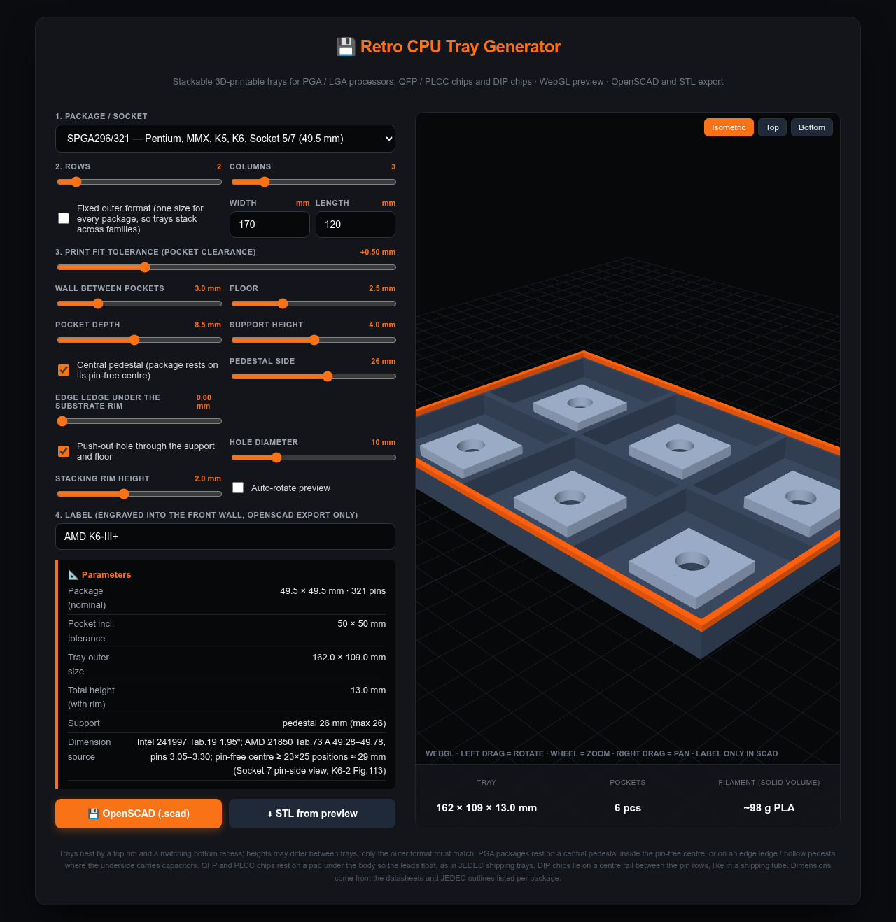
Chip Tray Generator — a small browser tool that generates stackable, 3D-printable storage trays for retro chips.
Use it online · source on GitHub (single HTML file, MIT)
What it does
- Three package families: PGA/LGA CPUs (PGA68/132/168, Socket 5/7, 370, A, 423, 478, 604, 754/939, AM2/AM3, LGA 775), QFP/PLCC chips (TQFP-100 to PQFP-240, PLCC-20 to PLCC-84) and DIP chips (DIP-8 to DIP-64, chips end to end in channels).
- Pick a package, rows × columns, wall thickness, pocket depth and print tolerance; live 3D preview; export OpenSCAD (exact, parametric, engraved label) or STL straight from the preview.
- Stacking: a rim on top and a matching recess underneath, so trays nest. With "fixed outer format" every tray gets the same footprint regardless of package, so a 386 tray stacks on a Socket 7 tray on a DIP-40 tray. Tray heights may differ.
- The chip never rests on its pins or leads: ceramic PGAs sit on a pedestal inside the pin-free centre (with a push-out hole), FC-PGA 370 and the newer sockets on an edge ledge because Intel/AMD put capacitors on the underside, QFP/PLCC on a pad under the body, DIPs on a centre rail between the pin rows like in a shipping tube. The tool warns when a support would touch pins, capacitors or lead feet.
Where the numbers come from
Package sizes and pin-free centres are taken from the datasheets, not guessed: Intel 231630 (386DX), the Intel packaging databook (486), 241997 + AP-579 (Pentium / Socket 7), 245264 (PGA370), AMD 25175 (Socket A) and 21850 (K6-2), JEDEC MS-022/MS-026/MS-018 for QFP/PLCC and MS-001/MS-011 for DIP. The list is in the README.
What is not done
I don't own a 3D printer, so none of this has been printed by me yet. The geometry is from the datasheets, the tolerance and support defaults are a first guess. If you print one, three numbers would let me fix the defaults: the printed pocket width with calipers, whether the chip sits on its support with the pins clear of the floor, and whether two trays nest.