VOGONS


First post, by Lopo

User metadata
Rank Newbie
Rank
Newbie

Chip Tray Generator — a small browser tool that generates stackable, 3D-printable storage trays for retro chips.

Use it online · source on GitHub (single HTML file, MIT)
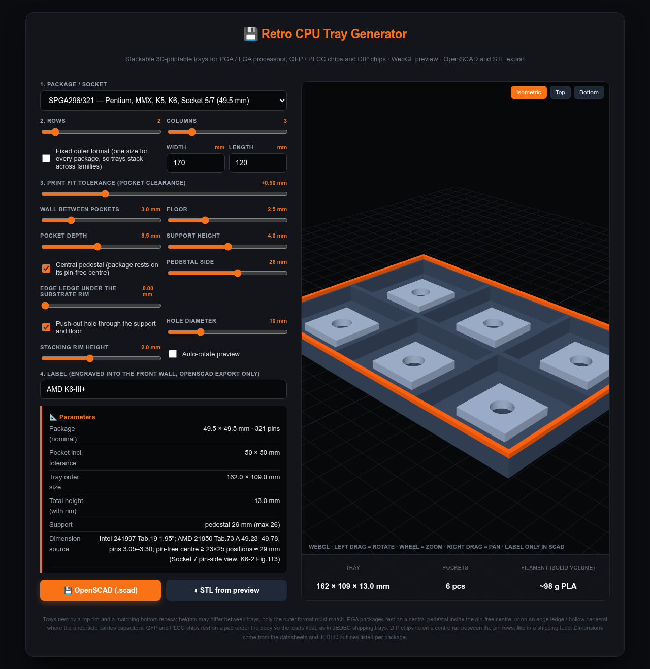
screenshot.png

What it does

  • Three package families: PGA/LGA CPUs (PGA68/132/168, Socket 5/7, 370, A, 423, 478, 604, 754/939, AM2/AM3, LGA 775), QFP/PLCC chips (TQFP-100 to PQFP-240, PLCC-20 to PLCC-84) and DIP chips (DIP-8 to DIP-64, chips end to end in channels).
  • Pick a package, rows × columns, wall thickness, pocket depth and print tolerance; live 3D preview; export OpenSCAD (exact, parametric, engraved label) or STL straight from the preview.
  • Stacking: a rim on top and a matching recess underneath, so trays nest. With "fixed outer format" every tray gets the same footprint regardless of package, so a 386 tray stacks on a Socket 7 tray on a DIP-40 tray. Tray heights may differ.
  • The chip never rests on its pins or leads: ceramic PGAs sit on a pedestal inside the pin-free centre (with a push-out hole), FC-PGA 370 and the newer sockets on an edge ledge because Intel/AMD put capacitors on the underside, QFP/PLCC on a pad under the body, DIPs on a centre rail between the pin rows like in a shipping tube. The tool warns when a support would touch pins, capacitors or lead feet.

Where the numbers come from
Package sizes and pin-free centres are taken from the datasheets, not guessed: Intel 231630 (386DX), the Intel packaging databook (486), 241997 + AP-579 (Pentium / Socket 7), 245264 (PGA370), AMD 25175 (Socket A) and 21850 (K6-2), JEDEC MS-022/MS-026/MS-018 for QFP/PLCC and MS-001/MS-011 for DIP. The list is in the README.

What is not done
I don't own a 3D printer, so none of this has been printed by me yet. The geometry is from the datasheets, the tolerance and support defaults are a first guess. If you print one, three numbers would let me fix the defaults: the printed pocket width with calipers, whether the chip sits on its support with the pins clear of the floor, and whether two trays nest.


Reply 1 of 13, by Yoghoo

User metadata
Rank Oldbie
Rank
Oldbie

Nice! Only the preview has a problem in Firefox (in Edge it works correctly). The preview slowly moves down and the preview window gets longer and longer because of it. This makes it almost impossible to preview it after some time.

Not printed one yet but will do so in the future.

Reply 2 of 13, by Lopo

User metadata
Rank Newbie
Rank
Newbie
Yoghoo wrote on Yesterday, 08:45:

Nice! Only the preview has a problem in Firefox (in Edge it works correctly). The preview slowly moves down and the preview window gets longer and longer because of it. This makes it almost impossible to preview it after some time.

Not printed one yet but will do so in the future.

Thanks, confirmed and fixed — the preview canvas was sized from its own height every frame, which Firefox fed back into the layout, so the panel grew forever. It's now positioned out of the layout flow; reload and it should stay put.
Looking forward to the print report.

Reply 3 of 13, by Boohyaka

User metadata
Rank Oldbie
Rank
Oldbie

Really cool tool, thank you! Printing my first plate (486, 5x3) right now, will let you know how it comes out 😀

The attachment Untitled.png is no longer available

Reply 4 of 13, by Dothan Burger

User metadata
Rank Member
Rank
Member

I just started a 478/479 tray 2x3, though this slow Ender 3 will take about 7.5 hours.

The attachment IMG_1679.JPG is no longer available

The outer package dimensions were too tight. The push through hole isn't present, so I can't remove one without emptying them all on the carpet. The label feature didn't work. Also my crappy printer had a hard time with the overhang, I should have printed supports but I think you could just bevel the edges and that would work without supports.

Reply 5 of 13, by Boohyaka

User metadata
Rank Oldbie
Rank
Oldbie

I'm back after a couple of prints!

- I also think there could be improvement on the external edges and overhang. My P2S also had issues with it on my first print. With automatic support trees it was of course fine, but the model could be optimised with bevelling as Dothan Burger suggested, wasting less material and improving print speed.

- I printed 386 and 486 tray, the 486 is perfect, but unfortunately your 386 size is off. I didn't double-check before printing unfortunately. Official die package size for 386 is 36.8x36.8, and not 34.5 like in your tool. Following the sources for dimensions you cite (great job about that, by the way!) I can only assume it is some kind of manual error or IA hallucination, because the mentioned documentation does give the correct size of 1.450" / 36.802mm:

https://www.ardent-tool.com/CPU/docs/Intel/38 … /231630-011.pdf

The attachment 386size.png is no longer available

- The STL exported model does not have the engraved label at all, only the .scad does. In my case that means a lot of extra steps: download .scad, import in OpenSCAD, render, export again in a common format. Wouldn't it be possible to offer to export the final model including label engraving in a ready-to-print format such as .3mf directly from the tool?

All that said, I really like it and find it very convenient 😀 I for one would love that you keep improving it!

Dothan Burger wrote on Yesterday, 16:17:

The outer package dimensions were too tight. The push through hole isn't present, so I can't remove one without emptying them all on the carpet. The label feature didn't work. Also my crappy printer had a hard time with the overhang, I should have printed supports but I think you could just bevel the edges and that would work without supports.

Strange about the push-through holes not being present. Could you have unchecked "Central pedestal (package rests on its pin-free centre)" option by mistake? Did you check the model in your slicer software?
EDIT: sorry I overlooked you were printing s478 with no pedestal at all, and in that case there was no hole. It's been fixed by Lopo.

For the label feature, did you download the .stl file as explained above? Those don't have the engraved label exported.

The attachment 386.jpeg is no longer available
The attachment 486.jpeg is no longer available
Last edited by Boohyaka on 2026-09-22, 10:49. Edited 1 time in total.

Reply 6 of 13, by Lopo

User metadata
Rank Newbie
Rank
Newbie

Big update — package dimensions corrected, please re-export

Start with the important one. PGA132 (386DX) was wrong — I had 34.5 mm, the drawing says 1.450 in = 36.802 mm (Intel 231630, Fig. 8.1). Thanks Boohyaka for catching it. A 386 printed from the old version has a pocket over 2 mm too small, which is the difference between a chip dropping in and not going in at all.

So I went back over every PGA against its actual drawing instead of trusting my notes, and took the largest published dimension in each case so any vendor's specimen fits:

  • PGA68 (287 / 387) 27.9 → 29.5
  • PGA132 (386DX) 34.5 → 36.8
  • PGA168/169 (486, Socket 1–3) 44.5 → 45.2
  • Socket 5 / 7 / 370 / A 49.5 → 49.8

Every package now shows the source it came from in the parameter table, so you can check my work rather than take my word for it. If you printed PGA trays from an earlier version, re-export them.

The rest of what is new:

  • Push-out hole on every package. It used to be tied to the centre pedestal, so everything that rests on an edge ledge (Socket 423/478/604/754/939/AM2, LGA775) had no hole at all. Spotted by Dothan Burger. DIP channels get one hole per chip position through the rail.
  • Finger notches — the walls between pockets are slotted down to the level the chip rests on, on both axes, so you can pinch a chip out from the side instead of only pushing it up through the hole
  • The nesting step under the outer edge is now a choice: a 45° chamfer that prints without support, or the plain square step if you would rather add support in the slicer. Both nest the same — the chamfer sits above the part that goes inside the rim, so it never touches it.
  • 3MF export, alongside STL and OpenSCAD. The raised label comes out as a separate part with its own material, so a dual-colour printer can put it on the second extruder, and it loads as one object with two parts rather than several objects at different heights. The preview shows the label in that material's colour.
  • Label on the front wall, raised (real geometry, exported) or engraved (cut by the OpenSCAD export). Case is kept as you type it.
  • Warnings when something will not work: outer wall too thin for the nesting recess, pockets that do not fit a fixed format, DIP channels longer than the tray
  • The page uses the whole window now — the controls scroll on their own and the 3D preview takes the rest, instead of being squeezed into half the width

Verified on a real print so far: PGA168 (486), 5×3, on a Bambu Lab — thanks Boohyaka.

Still unverified by anyone: two trays actually nesting. I have no printer here, so that part is only proven in CAD (I check it by intersecting two stacked trays in OpenSCAD and confirming the overlap is zero). If somebody prints a pair, I would like to hear whether the 0.5 mm default tolerance is right, or whether it wants to be tighter or looser.

Reply 7 of 13, by Boohyaka

User metadata
Rank Oldbie
Rank
Oldbie

Great update! Already implementing previous suggestions and new ones I was going to make 😉 namely through-hole for all plates (I realise I didn't properly interpret Dothan Burger's remark before as he was printing s478 with no pedestal, sorry about that) and the finger notches.

I am printing new plates now, with 45° chamfer and no support. It will take a while as I'm trying to maximise the plate size and slots while avoiding too much wasted space on the type of plates I'll be printing. I've settled for 247x178mm. One plate takes a bit more than 4 hours to print on my P2S.

I'll happily report how they stack when I have a pair!

Thanks again 😀

Reply 8 of 13, by Dothan Burger

User metadata
Rank Member
Rank
Member

Great update indeed! I'll report back later tonight.

Reply 9 of 13, by Yoghoo

User metadata
Rank Oldbie
Rank
Oldbie

I printed two 1x1 Athlon trays. They came out fine and stacked okay. But the push-out hole is quite small. I would like to use my pinky to push it up. Maybe use a chamfer there as well and make the hole larger? This also saves some material during printing.

Some other minor points: change the default "Label on the front wall" text with the selected socket. I was a bit confused at first why the AMD K6-III+ text didn't change when selecting a different socket. 😀 Also hope that the engraved label style will make it to the STL of 3MF export in the future.

Reply 10 of 13, by Lopo

User metadata
Rank Newbie
Rank
Newbie

Thanks both — and Yoghoo, thanks especially for the stacking report. That was the one thing nobody had checked, and since I have no printer here it was only ever proven in CAD. Good to know it holds up in PLA.

All three points are in:

Engraved labels now come out in the STL and 3MF, not just OpenSCAD.

The push-out hole is funnelled at its mouth on the underside — the end you actually poke — so there is no sharp rim and it is easier to find without looking.

On the size, though: there is already a slider for the hole diameter, right next to the checkbox, and it goes up to 30 mm. The default of 10 mm is deliberately conservative because the same control also serves a DIP-8 rail, but drag it wherever you like.

The label now remembers what you typed, per package. I thought about a default that follows the socket and I do not think it can be made honest: one outline covers several sockets and several CPU families. PGA168 is everything from a 486 through Sockets 1–3 to a 5x86. LGA775 and LGA771 share an outline. AM2, AM2+, AM3, AM3+ and the FM sockets all share one. Whatever the tool printed there would be wrong most of the time, and a wrong label on a storage tray is worse than no label. So it does the useful half instead: type it once for a package and it comes back the next time you select that package, including after closing the browser.

Everything is live on the page and in the repo.

Reply 11 of 13, by Boohyaka

User metadata
Rank Oldbie
Rank
Oldbie

The 386 plate came out perfect! The finger notches are game changing, and the chamfer outer edge printed out perfectly with no need for supports 😀 I am currently printing a second plate, let's see how they stack when it's done.

One very weird thing that I'm unable to reproduce unfortunately, still mentioning it to you in case you manage to find the condition that triggered the bug: the 3MF model came out with some holes in the middle not going through, see pic below. Didn't notice it when slicing, only when the final print was done, went back and checked the model and it does indeed show up like that in Bambu Studio. I tried re-exporting the same model but it's showing fine, so sorry I cannot be more helpful. Still better to document it than brushing it under the rug I believe 😀

The attachment Untitled.png is no longer available

EDIT: looking more into it in fact it's not the hole itself...the pocket "floor" is just higher, which is pretty obvious with perspective comparing piedestals and confirmed by the built-in Bambu Studio measuring tool

The attachment depth.png is no longer available

Reply 12 of 13, by Lopo

User metadata
Rank Newbie
Rank
Newbie

Boohyaka, that screenshot was worth a lot — you found a real bug, and it was in every model the tool has ever produced, not just yours.

Faces that carried more than one hole were coming out with a handful of edges belonging to only one triangle, so the surface was not closed. Slicers repair that on load, and the repair is free to guess how: yours chose to seal the push-out holes of the inner pockets and flatten their pedestals. That is also why it would not reproduce — the mesh was wrong every time, the repair just decided differently on each load.

It is fixed. Everything that used to carry several holes in one face is now split into pieces that carry none, and the build is checked so that no edge belongs to an odd number of triangles — over every package, both formats, all three label styles, with and without finger notches, both nesting styles. 984 combinations, plus a pile of awkward label texts on top. All clean, and the models actually come out slightly lighter in triangles than before.

Please re-export anything you have not printed yet.

Glad the 386 plate and the notches worked out — and sorry for the wasted filament on that one.

Reply 13 of 13, by Boohyaka

User metadata
Rank Oldbie
Rank
Oldbie

Oooh you're right, Bambu Studio did complain with some error and I just clicked the "fix it" button without second thoughts and not noticing any difference at first glance 😁
Just highlights how proper QA is difficult work that requires thorough methodology and precision... does not explain why I wasn't really able to reproduce it but in any case, glad it's fixed!