VOGONS


Any sense buying modern PSU for old hardware?

Topic actions

Reply 260 of 280, by shevalier

User metadata
Rank Oldbie
Rank
Oldbie
CharlieFoxtrot wrote on 2026-09-17, 11:54:

Or at least I'm old enough not to hear that anymore, but I don't think that is it because I can hear whining old HDDs just fine.

/offtopic
As for hard drives – yes, this is a problem for those who didn’t manage to switch to terabyte-class SSDs for ‘warm data’ before this year.
After all, reducing noise by 80 % costs just 20 % of the total cost.
Usually, it’s the single noisiest fan in the case, and replacing it isn’t difficult.
After that, every extra decibel starts to cost more and more.
Until you get to the noise from the hard drives. And this year, you’d need to be Elon Musk’s heir to afford that.

Aopen MX3S, PIII-S Tualatin 1133, Radeon 9800Pro@XT BIOS, Audigy 4 SB0610
JetWay K8T8AS, Athlon DH-E6 3000+, Radeon HD2600Pro AGP, Audigy 2 Value SB0400
Gigabyte Ga-k8n51gmf, Turion64 ML-30@2.2GHz , Radeon X800GTO PL16, Diamond monster sound MX300

Reply 261 of 280, by wierd_w

User metadata
Rank l33t
Rank
l33t
ldeveraux wrote on 2026-09-17, 13:06:
wierd_w wrote on 2026-09-16, 19:02:
Says the guy who does not understand "Legacy Systems" :D […]
Show full quote

Says the guy who does not understand "Legacy Systems" 😁

Our hobby is not the only market for old hardware.

*edit

Besides, what is good for this goose, is good for the modern gander as well. Why replace an expensive Corsair Gold rated PSU, just because the fan got all full of gunk, and the bearings failed? Shouldn't you just, y'know.... replace the fan?

Are you trying to reply to me? Don't know how to quote? I understand what a legacy system is, I don't understand why you'd insist on using an old, outdated, and clearly malfunctioning system in an environment when far better options exist.
You do you, I'm done trying to justify sanity and conscientious reasoning to you.

Being snide does not help you. I do in fact know how to use the quote function, I just dislike having huge nested bits of data for the forum's software to have to parse.

As for your statement, you *CLEARLY* do NOT understand Legacy Systems, if you think you can just replace them.

There are situations where that is not possible. Some noteworthy examples include:

Vinyl cutting machines
XRay machines
Medical imaging machines
Mass transit management systems
*ANYWHERE* there is difficult to update regulatory compliance that mandates specific hardware configurations.

These often have bespoke hardware inside that is not supported by the original OEM on any other hardware. The ONLY option is to repair them, or find suitable vintage parts.

If you think this is not widespread, you are even MORE wrong.

https://www.captechu.edu/blog/why-legacy-tech … of-modern-world

Again, our hobby is not the only place vintage equipment is sought after.

Reply 262 of 280, by roxfly

User metadata
Rank Newbie
Rank
Newbie

Not all psus these days have a 20+4 ATX like they used to. Shop cautiously otherwise a 24 to 20 pin adapter is needed.

Reply 263 of 280, by TELVM

User metadata
Rank Oldbie
Rank
Oldbie

^ Good point Roxfly. 👍

Only in rare cases of planetary conjunction can a one-piece ATX24 connector be directly plugged into an ATX20 header.

file.php?mode=view&id=249421

Let the air flow!

Reply 264 of 280, by Mondodimotori

User metadata
Rank Member
Rank
Member
TELVM wrote on 2026-09-19, 13:53:
^ Good point Roxfly. :+1: […]
Show full quote

^ Good point Roxfly. 👍

Only in rare cases of planetary conjunction can a one-piece ATX24 connector be directly plugged into an ATX20 header.

file.php?mode=view&id=249421

You have to get lucky that nothing is in the way where the extra 4 pin are going to be left hanging.
I had such luck on an Abit NF7 series board with which I used a modern PSU with a full 24pin connector.
Not such luck on another board, and I don't really trust those amazon 24 to 20pin adapters. They feel flimsy...
51x99850wML._SX385_.jpg

Reply 265 of 280, by ldeveraux

User metadata
Rank Member
Rank
Member
Mondodimotori wrote on 2026-09-24, 09:14:
You have to get lucky that nothing is in the way where the extra 4 pin are going to be left hanging. I had such luck on an Abit […]
Show full quote
TELVM wrote on 2026-09-19, 13:53:
^ Good point Roxfly. :+1: […]
Show full quote

^ Good point Roxfly. 👍

Only in rare cases of planetary conjunction can a one-piece ATX24 connector be directly plugged into an ATX20 header.

file.php?mode=view&id=249421

You have to get lucky that nothing is in the way where the extra 4 pin are going to be left hanging.
I had such luck on an Abit NF7 series board with which I used a modern PSU with a full 24pin connector.
Not such luck on another board, and I don't really trust those amazon 24 to 20pin adapters. They feel flimsy...
51x99850wML._SX385_.jpg

You could always just clip the 4 edge pins off at the connector, make your own 4pin power cable that you don't need to use. As long as you're not careless with it by clipping leads, it's perfectly fine.

Reply 266 of 280, by rorirub

User metadata
Rank Newbie
Rank
Newbie
shevalier wrote on 2026-09-17, 07:16:
Noctua NF-P14s — 2 mm H₂O, original Yate Loon D14BH-12 — 5 mm H₂O. […]
Show full quote
Mike_ wrote on 2026-09-17, 06:02:
shevalier wrote on 2026-09-16, 12:35:
We’ve come to this… […]
Show full quote

We’ve come to this…

There are exactly two 140mm fans on the market, 25mm thick and with high static pressure, that can be used in a PSU.
These are the SILENT WINGS PRO 4 140mm PWM from Be-Quiet and another ‘industrial’ Noctua.
But they both have a starting voltage of 5 volts.
And they cost 1.5 to 2 times more than their equivalents.

So here I am, having to deal with this nonsense.
The CWT PSH (without any numbers) was sold under the Corsair, Thermaltake and Chiftec CFT brands.
Seems to work

PS Perhaps Google will index this page and stop showing me its ‘smart search’ suggestions, which have been driving me mad for two days running. 😀

I thought most PWM fans can be voltage-controlled as well. Arctic's P14 doesn't fit the "25mm" part, but you don't need to go for Noctua's industrial lineup, a regular NF-P14s should work fine. And I would assume there are cheaper alternatives, but I can't say for sure.

Noctua NF-P14s — 2 mm H₂O, original Yate Loon D14BH-12 — 5 mm H₂O.

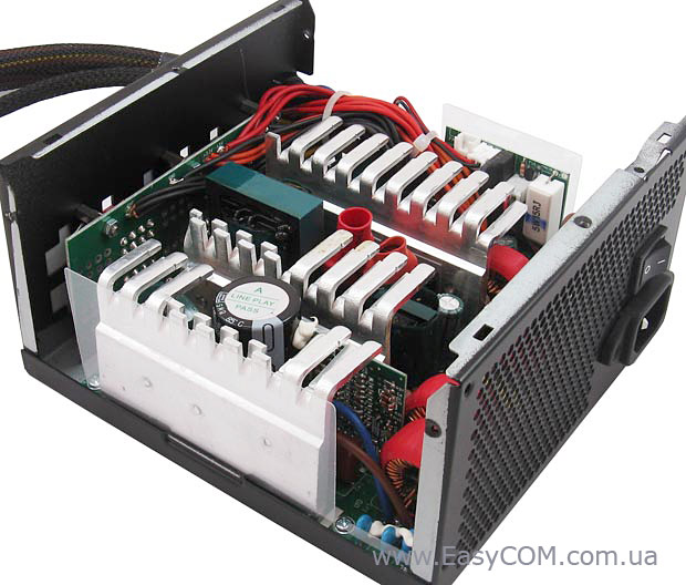
The heat sinks look like this
17.jpg
This is an old topology with independent regulation, but it still uses Schottky diodes.
And, unfortunately, they get very hot.
I’m afraid a case fan with a high CFM rating, but with blades designed for open-air cooling, won’t be able to cool such heat sinks properly.

You forgot that the Yate Loon achieves that high static pressure by running at 2800rpm and a ridiculous 48dBa. Cooling the power supply properly is one thing, having your PC sound like a jet engine is something else altogether. If there's one thing I don't miss from old PCs is how stupidly loud they were. Anyway, you need high static pressure for the ridiculously dense aluminium fins on heatsinks and water blocks. The power supply you pictured will do fine with any normal fan; even that Yate Loon at 4V would run at ~900rpm at which it would have bugger all static pressure.
So your only gotcha remains the fan start up voltage, which I admit is a stumper. I don't know if any modern fans support voltages as low as 4V. Then again I haven't even tested any. I know my old Noctua P12 doesn't spin up at 3.3V from a cr2032 battery but maybe at 4V it would do something.

I'd just use a noctua NF-P12 redux-900 with a 3d printed 140mm to 120mm adapter and hard wire it to 12V. It has as much pressure as the 1200rpm 140mm variant, but at far lower noise (12dBa vs 19dBa), and having it running always-on will cool it sufficiently at all but the highest loads (and if you are using it at maximum load in the long term, perhaps you should consider upgrading it anyway).

Alternatively: drill a 4-pin PWM input into the power supply chassis, and then you can use any modern fan. I had a similar problem a few years ago, but I lucked into not needing to drill anything. My Corsair RM650 from 2015 or so had its fan fail. It used a nonstandard 135mm fan and one of those Corsair Link thingies on the chassis, a thin 4-pin connector with an adapter for a 2-pin and 3-pin fan connector out of the box. To this day I have no clue what that connector was used for, but I think you could monitor the fan RPM with it? So I got a 3d printed 135mm to 120mm adapter and stuck an old noctua S12 redux inside, and rewired that Corsair Link to connect to the fan, allowing it to be software controlled from the motherboard with the included adapter. Obviously not a desirable replacement since you now always need to manually control it or else it won't even speed up, but 1) I only use it as a backup (it's very inefficient at the low wattages that modern computers idle at), and 2) it would have been possible to wire it so it defaults to the power supplies internal voltage pin and the input on the corsair link acts as an override, but I'm not an EE and didn't want to risk blowing it up.

Reply 267 of 280, by rorirub

User metadata
Rank Newbie
Rank
Newbie
Mike_ wrote on 2026-09-17, 06:02:

I thought most PWM fans can be voltage-controlled as well.

This depends entirely on the fan, a long time ago I used a mix of voltage-controlled fans and PWM controlled Noctua P12 Redux fans, and the P12s just stopped spinning a while after boot. I always assumed it was due to the complete lack of PWM signals. Upgraded all fans to PWM shortly after to get around both this problem, and to get around how annoying it was to speed control all those 3-pin fans. I had this funky fan hub that could control several 3-pin fans from a single 4-pin PWM header, it converted the PWM duty cycle to an approximately lowered voltage output.

Reply 268 of 280, by Fazeshift

User metadata
Rank Newbie
Rank
Newbie

All of the modern 4-pin PWM fans I have recently tried would run with only the +12V and ground pins connected, usually at a higher RPM. Perhaps a PWM signal is required for some though.

When I test PWM fans, I use one of these cheap "PWM Frequency Generator" modules:

The attachment PWM meter.jpg is no longer available

They cost $9-15. Set the frequency to 25KHz. The duty cycle then controls the fan speed.

As for the 24-pin ATX motherboard connectors, it is frustrating that you often cannot determine if a particular brand/model has a 4-pin breakaway or not. Sometimes product photos help. I just picked up a Seasonic Focus GX-750 for a retro (re)build, and was happy to see extra 4-pins can be detached. Worst case, look for an ATX motherboard extension cable with detachable 4-pin - it seems easier to find a wider selection and better quality extensions than the 24 to 20-pin adapters.

Reply 269 of 280, by shevalier

User metadata
Rank Oldbie
Rank
Oldbie

The PWM fan controller has several features that older controllers did not have.
This is because they were simply ‘two transistors and a Hall sensor in a single housing’.
The PWM controller has its own +5V regulator inside, so the voltage supplied to the fan must be higher; otherwise, the controller itself simply won’t start up.
When a constant logic ‘1’ is applied to the PWM (or if the wire is missing), it should run at maximum RPM.
With a constant ‘0’ (you can simply short-circuit it), it should either stop or switch to its minimum speed (adjusted via resistors on the fan circuit board).
What’s more, the adjustment there is very flexible
– for high-end models with very powerful motors – from 0.0001 PWM (for example, an old 120mm Zalman Performa fan can actually spin at 10 revolutions per minute)
- or FanStop – it won’t start below a certain % PWM
- or constant rotation – below a certain % PWM, it will still rotate at a certain speed.
- high and low slopes of the speed curve. In other words, the relationship need not be a 1:1 ratio with PWM.

Aopen MX3S, PIII-S Tualatin 1133, Radeon 9800Pro@XT BIOS, Audigy 4 SB0610
JetWay K8T8AS, Athlon DH-E6 3000+, Radeon HD2600Pro AGP, Audigy 2 Value SB0400
Gigabyte Ga-k8n51gmf, Turion64 ML-30@2.2GHz , Radeon X800GTO PL16, Diamond monster sound MX300

Reply 270 of 280, by shevalier

User metadata
Rank Oldbie
Rank
Oldbie
rorirub wrote on 2026-09-24, 22:16:

You forgot that the Yate Loon achieves that high static pressure by running at 2800rpm and a ridiculous 48dBa. Cooling the power supply properly is one thing, having your PC sound like a jet engine is something else altogether.

Actually, it’s 2 200 rpm.
And the impeller’s shape is optimised for pressure.

As for the ‘jet’ – well, there is a speed controller.
Moreover, in the CWT it is traditionally ‘over-engineered’ – if the PC is switched off whilst the power supply is still hot, the fan will continue to run on standby power until it has cooled down.
And it is at this point that you can hear it if the bearings are worn out.

Whereas in FSPs of that era it was a matter of ‘two virtual transistors’, where the speed varied proportionally with temperature, in the CWT, due to its very steep curve, it is more geared towards maintaining a radiator target temperature under load.

I’m happy with the replacement, although I could have saved a bit by opting for a model with a fixed speed of 1 800 rpm rather than one with a 1200–1800–2400 switch.

Aopen MX3S, PIII-S Tualatin 1133, Radeon 9800Pro@XT BIOS, Audigy 4 SB0610
JetWay K8T8AS, Athlon DH-E6 3000+, Radeon HD2600Pro AGP, Audigy 2 Value SB0400
Gigabyte Ga-k8n51gmf, Turion64 ML-30@2.2GHz , Radeon X800GTO PL16, Diamond monster sound MX300

Reply 271 of 280, by Mike_

User metadata
Rank Member
Rank
Member
shevalier wrote on 2026-09-16, 04:33:

If there is a filter with inductance at the output of the power rail, then the second capacitor is not included in the calculations. It is recommended to set its capacitance to either 50% of the first capacitor’s value for a flyback topology, or to the same value as the first capacitor for a forward-converter topology (but not exceeding the first capacitor’s capacitance).
This is a clear engineering recommendation that is consistent with my experience.

Btw, I checked it out and it turned out that those 1000µF caps on 12V rail were not in parallel, but there was something between them. So I just replaced them with new 1000µF caps, though I used a 3300µF cap on 5V rail instead of 2200µF as it seemed quite small. I tested it with a dummy load (10Ω for 12V and 3Ω for 5V) and it seems to work fine, voltages are what you'd expect and ripple is also within spec. However, ripple for 12V looks really weird, I wonder what's going on? 😁

The attachment 12V_ripple.jpg is no longer available

Also, I decided to recap a CWT AT power supply I had as a spare now that I'm at it. AT power supplies are a lot nicer to work with than more modern PSUs, as they have more space and you don't need to solder anything to get the PCB out of the chassis. Apparently they didn't try to save costs by removing connecors at the time. Anyways, there's a 0.68µF electrolytic capacitor, which is kind of a problem as they don't seem to be available nowadays. So I just ordered 100V 0.68µF ceramic capacitors, would it be okay to use that there instead? Ceramics do have much lower ESR, which might cause issues in some cases, but I suppose easiest way to find out is to just try it? There are 1µF caps in the PSU as well, so I guess there's some reason why they chose that specific value there. Or if ESR is important here, perhaps a series resistor with the ceramic would work?

The attachment smallcap.jpg is no longer available

Reply 272 of 280, by shevalier

User metadata
Rank Oldbie
Rank
Oldbie
Mike_ wrote on 2026-09-29, 13:54:

Also, I decided to recap a CWT AT power supply I had as a spare now that I'm at it. AT power supplies are a lot nicer to work with than more modern PSUs, as they have more space and you don't need to solder anything to get the PCB out of the chassis. Apparently they didn't try to save costs by removing connecors at the time. Anyways, there's a 0.68µF electrolytic capacitor, which is kind of a problem as they don't seem to be available nowadays. So I just ordered 100V 0.68µF ceramic capacitors, would it be okay to use that there instead? Ceramics do have much lower ESR, which might cause issues in some cases, but I suppose easiest way to find out is to just try it? There are 1µF caps in the PSU as well, so I guess there's some reason why they chose that specific value there. Or if ESR is important here, perhaps a series resistor with the ceramic would work?

The attachment smallcap.jpg is no longer available

Regarding sub-1μF electrolytic capacitors.

The advantage of these is that they act as a completely free-cost RC snubber with very low Q-factor.
However, given the precision of capacitance electrolytic capacitors, their frequency response is entirely unpredictable. And given the unpredictable ageing of electrolytic capacitors, their time response is also unpredictable.
Reputable manufacturers have always used film capacitors. Even if they’re the cheapest metallized PET ones, they’re still film capacitors.
You need to check where such a capacitor is fitted.
An MLCC might not be suitable, as its capacitance drops dramatically with voltage and temperature.
For example, if there was a delay of 100 ms, it might become – but by how much is unknown.
If it’s simply a noise filter, then yes, an MLCC is an excellent option.

Over time, I’ve collected quite a few of these metallised PET capacitors in very small casings from all sorts of CRT televisions and monitors, such as the 0.47/1 μF–50/63 V type.
I use them in these parts of the PSU.

Mike_ wrote on 2026-09-29, 13:54:

Btw, I checked it out and it turned out that those 1000µF caps on 12V rail were not in parallel, but there was something between them. So I just replaced them with new 1000µF caps, though I used a 3300µF cap on 5V rail instead of 2200µF as it seemed quite small. I tested it with a dummy load (10Ω for 12V and 3Ω for 5V) and it seems to work fine, voltages are what you'd expect and ripple is also within spec. However, ripple for 12V looks really weird, I wonder what's going on? 😁

The attachment 12V_ripple.jpg is no longer available

1600 Hz?
If there is a C-L-C filter on the +12V line, check the voltage across the first capacitor from the group stabilisation choke.
And is there a load resistor of around 300 ohms on this power rail?
That’s a very low frequency for noise caused by switch transitions.
And it’s a bit low for C-L-C filter resonance (and the ripple voltage is very high, given that the capacitors are electrolytic whith high ESR).
And what does the oscilloscope show on the +5V line?

Aopen MX3S, PIII-S Tualatin 1133, Radeon 9800Pro@XT BIOS, Audigy 4 SB0610
JetWay K8T8AS, Athlon DH-E6 3000+, Radeon HD2600Pro AGP, Audigy 2 Value SB0400
Gigabyte Ga-k8n51gmf, Turion64 ML-30@2.2GHz , Radeon X800GTO PL16, Diamond monster sound MX300

Reply 273 of 280, by Mike_

User metadata
Rank Member
Rank
Member
shevalier wrote on 2026-09-29, 16:33:
Regarding sub-1μF electrolytic capacitors. […]
Show full quote

Regarding sub-1μF electrolytic capacitors.

The advantage of these is that they act as a completely free-cost RC snubber with very low Q-factor.
However, given the precision of capacitance electrolytic capacitors, their frequency response is entirely unpredictable. And given the unpredictable ageing of electrolytic capacitors, their time response is also unpredictable.
Reputable manufacturers have always used film capacitors. Even if they’re the cheapest metallized PET ones, they’re still film capacitors.
You need to check where such a capacitor is fitted.
An MLCC might not be suitable, as its capacitance drops dramatically with voltage and temperature.
For example, if there was a delay of 100 ms, it might become – but by how much is unknown.
If it’s simply a noise filter, then yes, an MLCC is an excellent option.

Over time, I’ve collected quite a few of these metallised PET capacitors in very small casings from all sorts of CRT televisions and monitors, such as the 0.47/1 μF–50/63 V type.
I use them in these parts of the PSU.

Negative terminal of the cap goes to pin 4 of KA7500B controller, and positive goes to pins 13, 14 and 15 which are all connected to each other. Looks like it has something to do with dead time control.

The attachment KA7500B.gif is no longer available

https://www.onsemi.com/download/data-sheet/pdf/ka7500b-d.pdf

I bought 100V rated X7R ceramics so that the voltage derating wouldn't be significant at the operating voltage, but I don't know whether that's enough to mitigate it.

EDIT: There's also a 100nF film cap between pin 5 and ground.

The attachment KA7500B.jpg is no longer available
shevalier wrote on 2026-09-29, 16:33:
1600 Hz? If there is a C-L-C filter on the +12V line, check the voltage across the first capacitor from the group stabilisation […]
Show full quote

1600 Hz?
If there is a C-L-C filter on the +12V line, check the voltage across the first capacitor from the group stabilisation choke.
And is there a load resistor of around 300 ohms on this power rail?
That’s a very low frequency for noise caused by switch transitions.
And it’s a bit low for C-L-C filter resonance (and the ripple voltage is very high, given that the capacitors are electrolytic whith high ESR).
And what does the oscilloscope show on the +5V line?

I was also wondering how its possible, as it can't be caused by the switching frequency. Looks like there's no load resistor on the 12V rail, either.

Voltage across the first cap isn't measurable without soldering a wire there (otherwise you'd have to poke at a powered PSU), I'll do that some other day.

On +5V line there's "normal" looking ripple that is under 20mV Vpp so nothing out of ordinary.

Reply 274 of 280, by shevalier

User metadata
Rank Oldbie
Rank
Oldbie
Mike_ wrote on 2026-09-29, 18:08:

Negative terminal of the cap goes to pin 4 of KA7500B controller, and positive goes to pins 13, 14 and 15 which are all connected to each other. Looks like it has something to do with dead time control.
I bought 100V rated X7R ceramics so that the voltage derating wouldn't be significant at the operating voltage, but I don't know whether that's enough to mitigate it.
EDIT: There's also a 100nF film cap between pin 5 and ground.

These days, developers don’t want to take responsibility and simply copy solutions from datasheets and application notes.
Back then, “Hive Mind” developed the basic solutions for using the TL494/KA7500, but everyone implemented the secondary functions however they wanted.

Ct (pin 5) is the capacitor that sets the switching frequency. Even the most reckless manufacturers didn’t risk putting anything other than a film capacitor there.

Pin 4 (Dead Time) is used for soft start. As it charges, the controller is allowed to gradually widen the pulses, increasing the power.
Often, an OVP (over-voltage protection) is connected to it, which everyone designed as best they could. Often, this is a confusing jumble of discrete transistors, resistors, and diodes.

I was also wondering how its possible, as it can't be caused by the switching frequency.

In the very ‘primitive’ PSU ATs, feedback was provided only via the +5-volt bus.
As for the +12V, it was whatever it turned out to be…
Feedback was usually connected to pin 1.

Aopen MX3S, PIII-S Tualatin 1133, Radeon 9800Pro@XT BIOS, Audigy 4 SB0610
JetWay K8T8AS, Athlon DH-E6 3000+, Radeon HD2600Pro AGP, Audigy 2 Value SB0400
Gigabyte Ga-k8n51gmf, Turion64 ML-30@2.2GHz , Radeon X800GTO PL16, Diamond monster sound MX300

Reply 275 of 280, by TELVM

User metadata
Rank Oldbie
Rank
Oldbie
Mike_ wrote on 2026-09-29, 18:08:

... I used a 3300µF cap on 5V rail instead of 2200µF as it seemed quite small ...

... On +5V line there's "normal" looking ripple that is under 20mV Vpp so nothing out of ordinary ...

^ I'd try larger caps also on the +12V rail, 2200 or 3300uF instead of 1000uF.

Let the air flow!

Reply 276 of 280, by Mike_

User metadata
Rank Member
Rank
Member
shevalier wrote on Yesterday, 07:02:
These days, developers don’t want to take responsibility and simply copy solutions from datasheets and application notes. Back t […]
Show full quote

These days, developers don’t want to take responsibility and simply copy solutions from datasheets and application notes.
Back then, “Hive Mind” developed the basic solutions for using the TL494/KA7500, but everyone implemented the secondary functions however they wanted.

Ct (pin 5) is the capacitor that sets the switching frequency. Even the most reckless manufacturers didn’t risk putting anything other than a film capacitor there.

Pin 4 (Dead Time) is used for soft start. As it charges, the controller is allowed to gradually widen the pulses, increasing the power.
Often, an OVP (over-voltage protection) is connected to it, which everyone designed as best they could. Often, this is a confusing jumble of discrete transistors, resistors, and diodes.

Hmm, so do you think a 100V X7R MLCC cap would be ok in that place? Vref is 5V and I guess Ct wouldn't be much below 0V, so DC bias derating shouldn't be significant.

I don't have a suitable film capacitor, but I guess I could leave current electrolytic cap in place. After all, this is just a spare PSU so I don't necessarily need to fully recap it.

TELVM wrote on Yesterday, 10:09:

^ I'd try larger caps also on the +12V rail, 2200 or 3300uF instead of 1000uF.

I doubt it has anything to do with that, as it doesn't look like normal ripple. And well, it's still within spec.

Reply 277 of 280, by shevalier

User metadata
Rank Oldbie
Rank
Oldbie
Mike_ wrote on Yesterday, 18:21:
Hmm, so do you think a 100V X7R MLCC cap would be ok in that place? Vref is 5V and I guess Ct wouldn't be much below 0V, so DC b […]
Show full quote
shevalier wrote on Yesterday, 07:02:
These days, developers don’t want to take responsibility and simply copy solutions from datasheets and application notes. Back t […]
Show full quote

These days, developers don’t want to take responsibility and simply copy solutions from datasheets and application notes.
Back then, “Hive Mind” developed the basic solutions for using the TL494/KA7500, but everyone implemented the secondary functions however they wanted.

Ct (pin 5) is the capacitor that sets the switching frequency. Even the most reckless manufacturers didn’t risk putting anything other than a film capacitor there.

Pin 4 (Dead Time) is used for soft start. As it charges, the controller is allowed to gradually widen the pulses, increasing the power.
Often, an OVP (over-voltage protection) is connected to it, which everyone designed as best they could. Often, this is a confusing jumble of discrete transistors, resistors, and diodes.

Hmm, so do you think a 100V X7R MLCC cap would be ok in that place? Vref is 5V and I guess Ct wouldn't be much below 0V, so DC bias derating shouldn't be significant.

I don't have a suitable film capacitor, but I guess I could leave current electrolytic cap in place. After all, this is just a spare PSU so I don't necessarily need to fully recap it.

TELVM wrote on Yesterday, 10:09:

^ I'd try larger caps also on the +12V rail, 2200 or 3300uF instead of 1000uF.

I doubt it has anything to do with that, as it doesn't look like normal ripple. And well, it's still within spec.

The capacitor on pin Ct is already a film capacitor (it’s that little white brick-shaped one).
As for pin number 4 (dead time), a 1 μF capacitor will clearly do the job; an electrolytic one would be fine, just as it was before.

As for the strange oscillation, I’d check which voltages the feedback is taken from.
It looks very much as though it’s only being taken from the 5V supply.
And the 1600 Hz is the resonance between the inductance of the group choke and the output capacitance.
Incidentally, you could check this as TELVM suggests – by replacing the 1000 µF capacitor with a 2200 µF one. If the oscillation frequency drops by a multiple of that value, then it’s definitely resonance.

Aopen MX3S, PIII-S Tualatin 1133, Radeon 9800Pro@XT BIOS, Audigy 4 SB0610
JetWay K8T8AS, Athlon DH-E6 3000+, Radeon HD2600Pro AGP, Audigy 2 Value SB0400
Gigabyte Ga-k8n51gmf, Turion64 ML-30@2.2GHz , Radeon X800GTO PL16, Diamond monster sound MX300

Reply 278 of 280, by Mike_

User metadata
Rank Member
Rank
Member
shevalier wrote on Yesterday, 18:34:

The capacitor on pin Ct is already a film capacitor (it’s that little white brick-shaped one).
As for pin number 4 (dead time), a 1 μF capacitor will clearly do the job; an electrolytic one would be fine, just as it was before.

Good point, it shouldn't matter if soft start takes a little bit longer. I wonder why they bothered to use a different size cap for that spot?

shevalier wrote on Yesterday, 18:34:
As for the strange oscillation, I’d check which voltages the feedback is taken from. It looks very much as though it’s only bein […]
Show full quote

As for the strange oscillation, I’d check which voltages the feedback is taken from.
It looks very much as though it’s only being taken from the 5V supply.
And the 1600 Hz is the resonance between the inductance of the group choke and the output capacitance.
Incidentally, you could check this as TELVM suggests – by replacing the 1000 µF capacitor with a 2200 µF one. If the oscillation frequency drops by a multiple of that value, then it’s definitely resonance.

Just to mention, the strange oscillation is happening in a different PSU - I'll return to it after I have put back together the CWT one.

EDIT: Something is not quite right after powering up the CWT PSU (0.68µF cap replaced with 1µF). Voltages are fine, but there's a high-pitched whine. Looking at 12V line with oscilloscope, there's definitely something odd happening at ~1kHz.

The attachment cwt_12V.jpg is no longer available
The attachment cwt_5V.jpg is no longer available

Reply 279 of 280, by shevalier

User metadata
Rank Oldbie
Rank
Oldbie
Mike_ wrote on Yesterday, 18:50:
Good point, it shouldn't matter if soft start takes a little bit longer. I wonder why they bothered to use a different size cap […]
Show full quote
shevalier wrote on Yesterday, 18:34:

The capacitor on pin Ct is already a film capacitor (it’s that little white brick-shaped one).
As for pin number 4 (dead time), a 1 μF capacitor will clearly do the job; an electrolytic one would be fine, just as it was before.

Good point, it shouldn't matter if soft start takes a little bit longer. I wonder why they bothered to use a different size cap for that spot?

shevalier wrote on Yesterday, 18:34:
As for the strange oscillation, I’d check which voltages the feedback is taken from. It looks very much as though it’s only bein […]
Show full quote

As for the strange oscillation, I’d check which voltages the feedback is taken from.
It looks very much as though it’s only being taken from the 5V supply.
And the 1600 Hz is the resonance between the inductance of the group choke and the output capacitance.
Incidentally, you could check this as TELVM suggests – by replacing the 1000 µF capacitor with a 2200 µF one. If the oscillation frequency drops by a multiple of that value, then it’s definitely resonance.

Just to mention, the strange oscillation is happening in a different PSU - I'll return to it after I have put back together the CWT one.

EDIT: Something is not quite right after powering up the CWT PSU (0.68µF cap replaced with 1µF). Voltages are fine, but there's a high-pitched whine. Looking at 12V line with oscilloscope, there's definitely something odd happening at ~1kHz.

The attachment cwt_12V.jpg is no longer available
The attachment cwt_5V.jpg is no longer available

It seems that noise from the reference has started to affect the dead-time control.
Not because the capacitance is greater, but because that’s how it was designed from the outset; it’s just that the old capacitor has simply dried out.
I’d clean up the power of the TL494 itself and see what happens, because, manufacturers cut corners on every aspect of the TL494’s powering itself.

Ideally, a Cvref bypass capacitor of ~0.1 µF should be fitted (this is missing in 99% of power supplies).
Either a film capacitor or an X5/7 rated for 25+ volts will do.
And the Rvcc+Cvcc circuit for the TL494 itself should be located in the immediate vicinity of its pins.
In 80% of cases, this is missing; in 10%, only Rvcc is present
R – 4.7–22 Ω (SMD, 0805/1206)
C – 4.7–1 µF X5/7 rated for 50+ volts.
Radd in series with C_dt is often present. It should be approximately up to 5% of R_dt. It will slightly reduce the high-frequency noise passing through C_dt. SMD 0805/0603.

Cvcc and Cvref – either SMD, if there is a ground trace nearby, or for through-hole mounting. ‘A roof over the house’, capacitor simply on top of the chip. This was a common method for decoupling memory chips during the ZX Spectrum era 😀.

Aopen MX3S, PIII-S Tualatin 1133, Radeon 9800Pro@XT BIOS, Audigy 4 SB0610
JetWay K8T8AS, Athlon DH-E6 3000+, Radeon HD2600Pro AGP, Audigy 2 Value SB0400
Gigabyte Ga-k8n51gmf, Turion64 ML-30@2.2GHz , Radeon X800GTO PL16, Diamond monster sound MX300