Reply 300 of 321, by maxtherabbit
- Rank
- l33t
interesting, makes me glad all my socket 8 boards are ATX
maxtherabbit wrote on 2026-10-25, 14:37:interesting, makes me glad all my socket 8 boards are ATX
Especially if they're Duels!
My other Socket 8 system's also ATX. (Well it has both options)
Irinikus wrote on 2026-10-17, 07:48:There are two types of electrolytic caps on this card, but both types have the same value: 1000MFD 6.3V 105 Degrees Centigrade ...
... Can someone please explain what the difference between these two types of cap is? (As the one type is considerably taller than the other.)
Everything else being equal, the larger the cap can, the lower the ESR.
The black smaller ones are filtering the input to the CPU VRM High FETs. Here low ESR is desirable, but not so critical.
The green tall ones are filtering the output from the VRM Low FETs to the CPU. As low as possible ESR is critical here.
Irinikus wrote on 2026-10-17, 07:48:... I just ordered 10 of these EEUFR1C102LB's to replace the VRM caps, they're more substantial than the EEUFR0J102's (I'm doing this just for good measure) ...
^ Well done 👍 , the 1C102L are ESR= 30 mΩ, about half than the 0J102 (56 mΩ), and thus better suited for CPU VRM output (replacing the 10 green Sanyos).
Let the air flow!
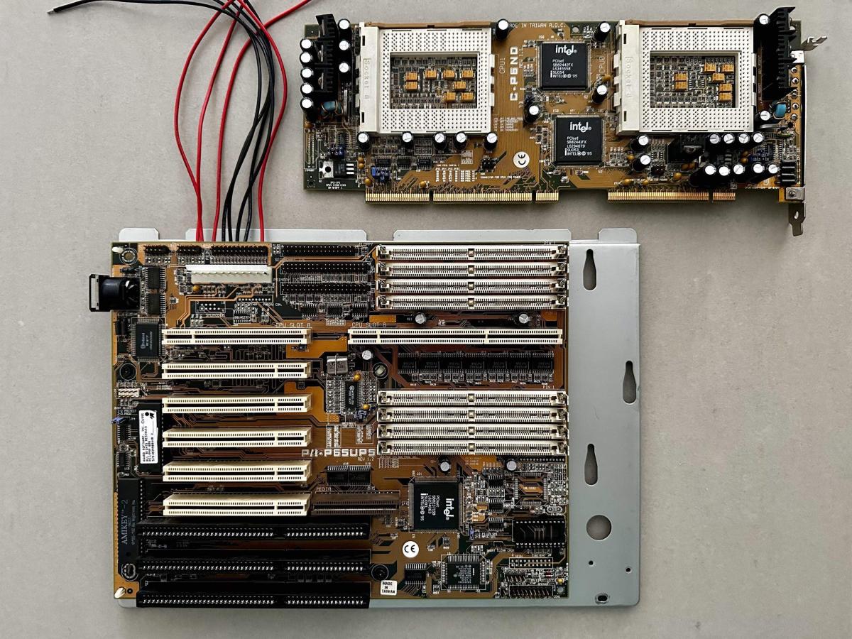
It’s been re capped and the extra power wiring is installed, I just need to fit and crimp male 4-pin MOLEX connectors!
![]()
That was a lot of work!
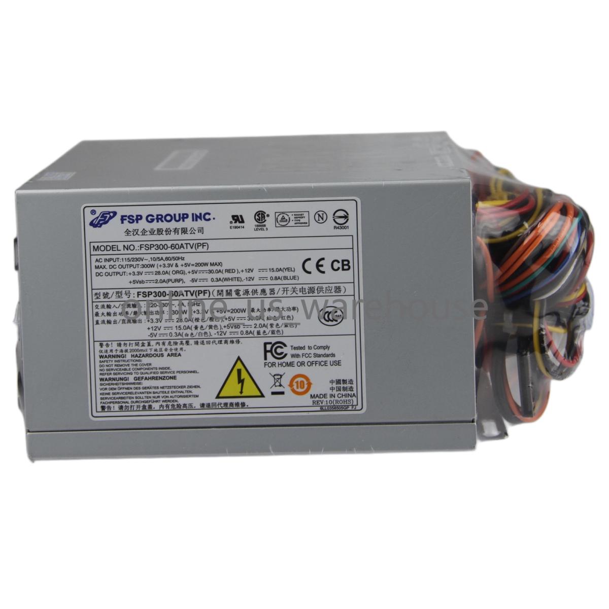
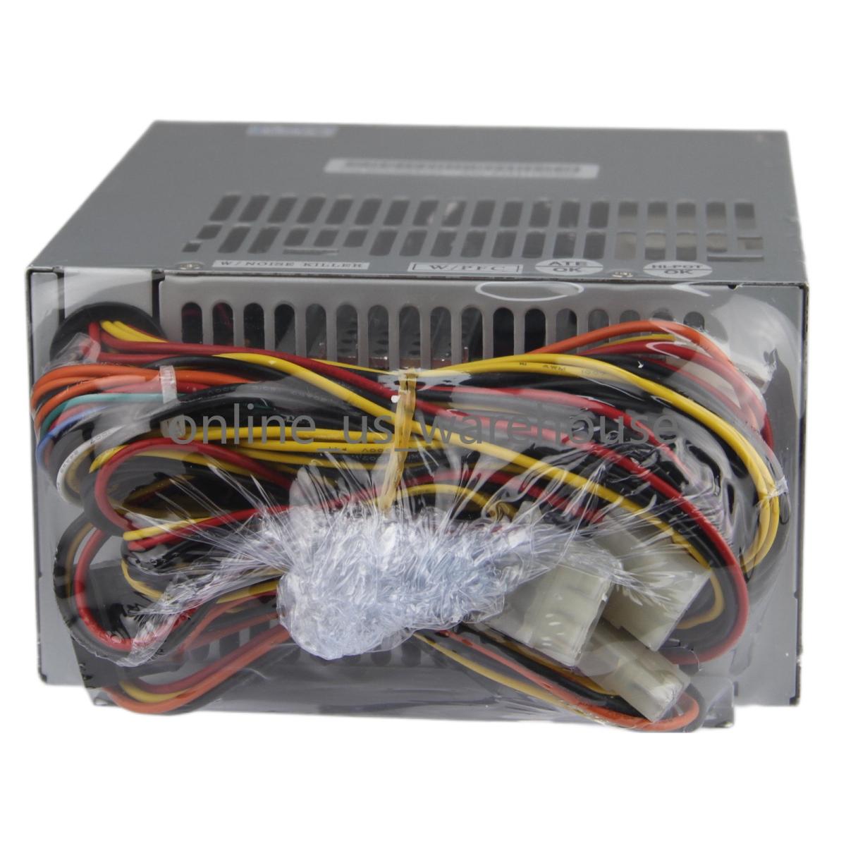
speaking of power, the current power supply that I have fitted can only supply 5V@20A maximum, and this thing needs at least 30A on the 5V rail, so I've ordered one of these industrial power supplies, which gives me 30A on the 5V rail and it also gives me -5V, for what it's worth: (FSP FSP300-60ATV (PF) 300W Industrial Computer Standard Power Supply)
![]()
![]()
![]()
Judging by the gauge of the cables, this thing should be up to the task!
Here’s how I wired the extra 5V couplings up:
![]()
![]()
Nice work!
Just came to wonder if you could've fed the 5V directly onto the CPU daughterboard in stead, thus also eliminating resistance in the edge connector.
If it's dual it's kind of cool ... 😎
--- GA586DX --- P2B-DS --- BP6 ---
Please use the "quote" option if asking questions to what I write - it will really up the chances of me noticing 😀
H3nrik V! wrote on 2026-10-27, 12:01:Nice work!
Thanks! 😀
H3nrik V! wrote on 2026-10-27, 12:01:Just came to wonder if you could've fed the 5V directly onto the CPU daughterboard in stead, thus also eliminating resistance in the edge connector.
We have discussed this possibility on the Silicon Graphics User Group Discord.
It may be worth looking into, especially if you want to do some overclocking. (These CPU's ran stably @ 233MHZ in my other machine.)
The issue is: wether it can be done neatly and non-invasively.
Nice project! Thank you for sharing it with us.
I have a K6 CPU module that is powered by a separate 5v wire. At first I had it plugged into a spare molex, then I found a convenient place to attach it on the main board. On your dual setup there are probably multiple places you could attach supplemental 5v power directly to the CPU board. Do you have a picture of the back side? One easy way to see if it would help is to measure the voltage on a running system. If you can carefully probe some of the input capacitors on the VRMs while it is under load, you can see how much voltage drop there is between the power supply and the VRM. I had one upgrade CPU module that would droop to almost 4v under load without additional 5v wires connected. An extra un-connected molex can be used to measure the voltage from the power supply (vs what you measure at the CPU VRM).
Irinikus wrote on 2026-10-26, 14:49:speaking of power, the current power supply that I have fitted can only supply 5V@20A maximum, and this thing needs at least 30A on the 5V rail, so I've ordered one of these industrial power supplies, which gives me 30A on the 5V rail and it also gives me -5V, for what it's worth: (FSP FSP300-60ATV (PF) 300W Industrial Computer Standard Power Supply)
That is a very OLD STOCK (read: 2003 or older, depending on revision) part and you will need to preemptively re-cap it.
Also, the FSP units of that era use the old fashioned standby circuit which gets hot even when the PC is powered off. Make sure to use high endurance caps in that area (usually it's two 6.3V/10V 1000uF, as well as some small 6mm and 5mm parts near where the purple wire is soldered into on the PCB).
nickles rust wrote on 2026-10-27, 19:43:Nice project! Thank you for sharing it with us.
I have a K6 CPU module that is powered by a separate 5v wire. At first I had it plugged into a spare molex, then I found a convenient place to attach it on the main board. On your dual setup there are probably multiple places you could attach supplemental 5v power directly to the CPU board. Do you have a picture of the back side? One easy way to see if it would help is to measure the voltage on a running system. If you can carefully probe some of the input capacitors on the VRMs while it is under load, you can see how much voltage drop there is between the power supply and the VRM. I had one upgrade CPU module that would droop to almost 4v under load without additional 5v wires connected. An extra un-connected molex can be used to measure the voltage from the power supply (vs what you measure at the CPU VRM).
Thanks! It's a pleasure! 😀
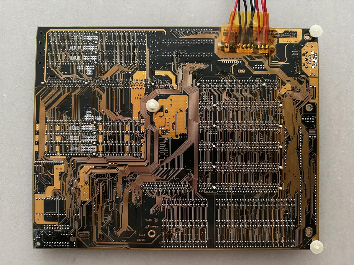
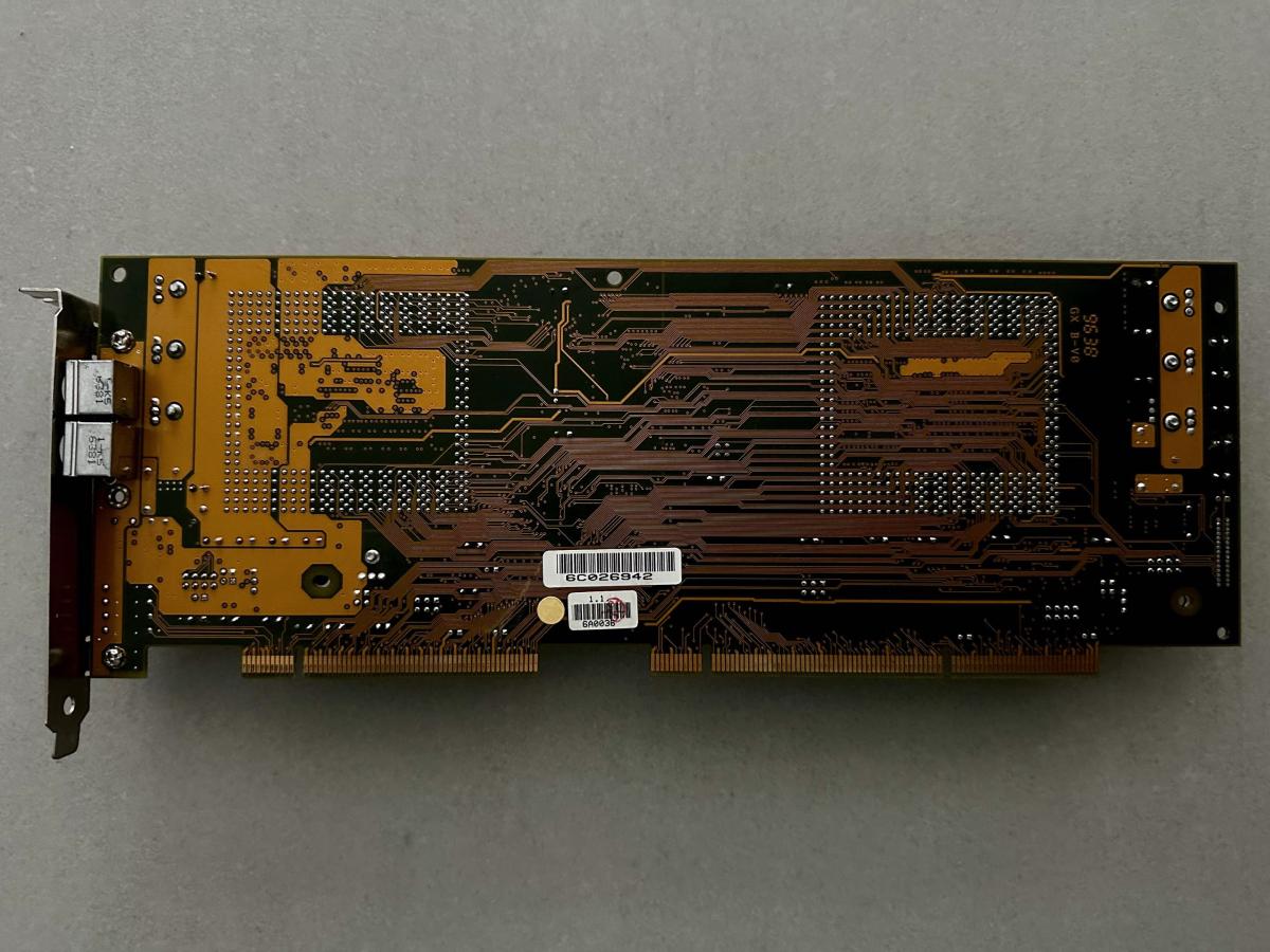
Here’s the back side of the CPU card: (looking for a good point to attach an additional power coupling)
![]()
mockingbird wrote on 2026-10-27, 21:26:Irinikus wrote on 2026-10-26, 14:49:speaking of power, the current power supply that I have fitted can only supply 5V@20A maximum, and this thing needs at least 30A on the 5V rail, so I've ordered one of these industrial power supplies, which gives me 30A on the 5V rail and it also gives me -5V, for what it's worth: (FSP FSP300-60ATV (PF) 300W Industrial Computer Standard Power Supply)
That is a very OLD STOCK (read: 2003 or older, depending on revision) part and you will need to preemptively re-cap it.
Also, the FSP units of that era use the old fashioned standby circuit which gets hot even when the PC is powered off. Make sure to use high endurance caps in that area (usually it's two 6.3V/10V 1000uF, as well as some small 6mm and 5mm parts near where the purple wire is soldered into on the PCB).
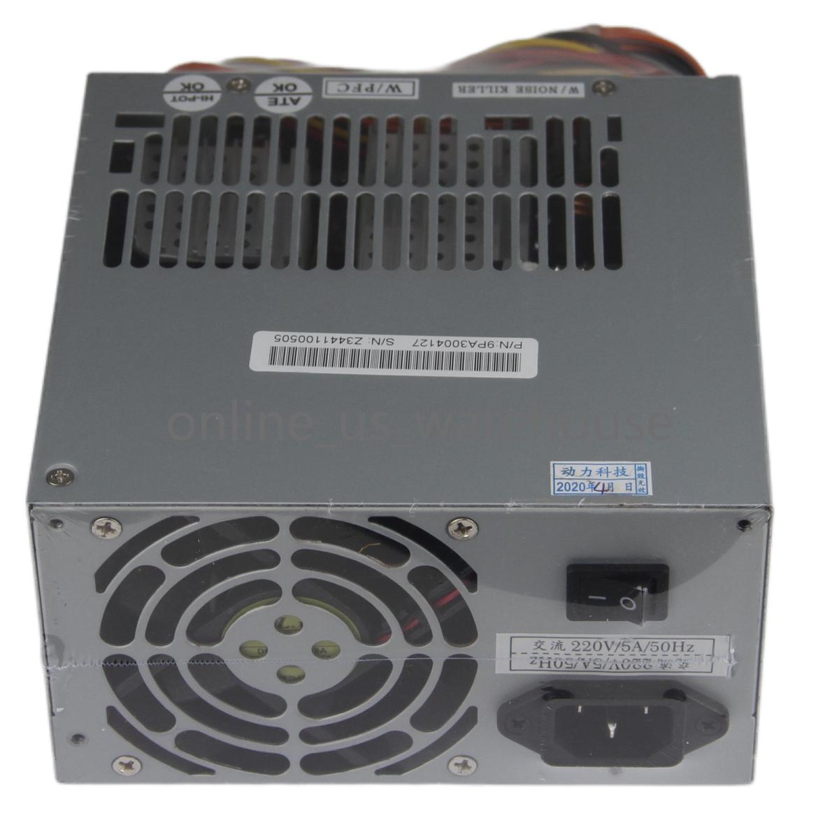
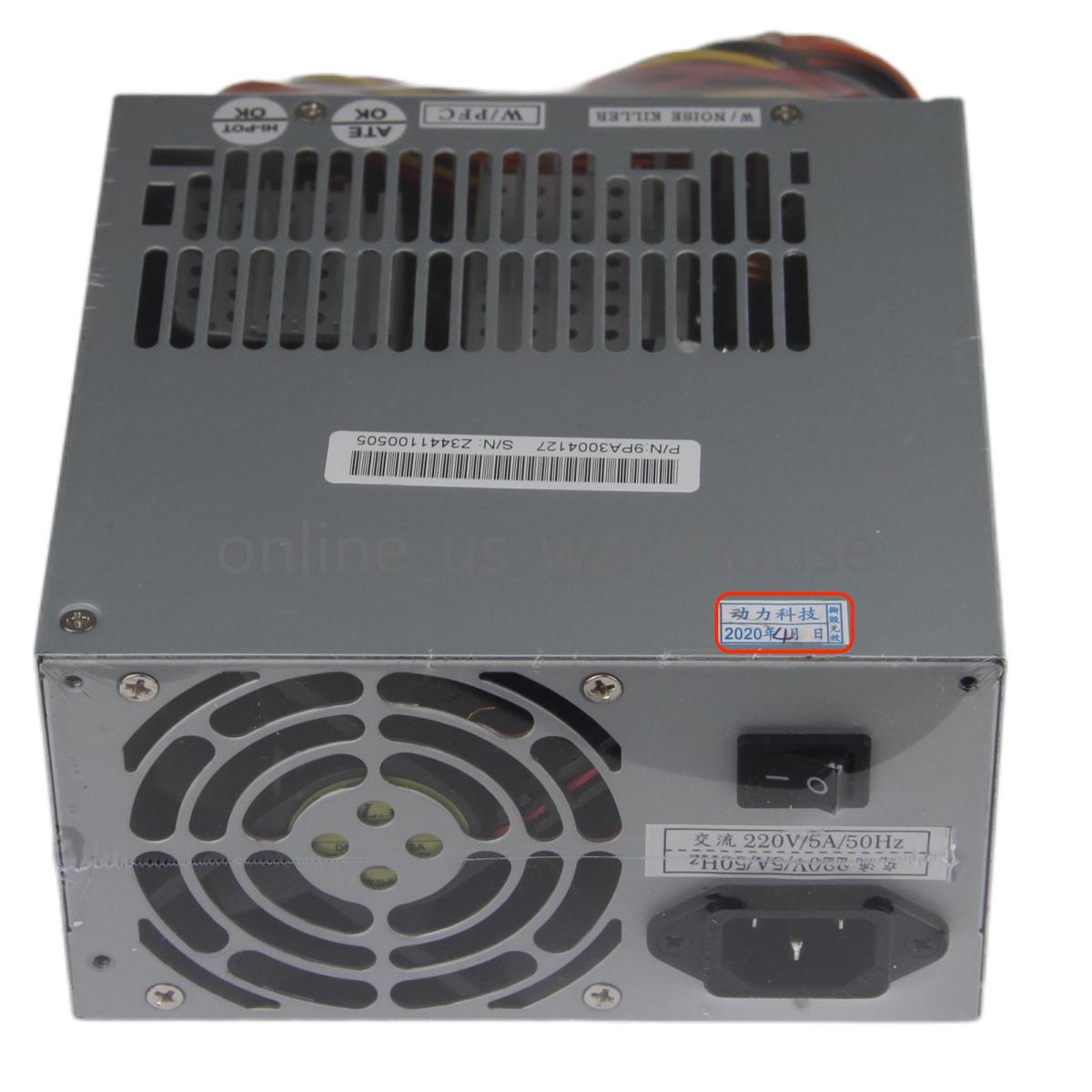
This one appears to be more modern, as it has a date sticker on it which references 2020. (They could maybe still be manufacturing them for legacy industrial machines.)
![]()
![]()
![]()
So according to the sticker it was manufactured in the fourth month of 2020.
I'll check it when I get it!
Irinikus wrote on 2026-10-28, 12:33:So according to the sticker it was manufactured in the fourth month of 2020.
I'll check it when I get it!
Yes, you could be right! Looks like a very late revision since it has power factor correction.
Can you show is the innards when it arrives? I'll wager it has Teapo SC... I would still reaplace those, especially the two by the purple 5vsb wire.
mockingbird wrote on 2026-10-28, 21:44:Can you show is the innards when it arrives? I'll wager it has Teapo SC... I would still reaplace those, especially the two by the purple 5vsb wire.
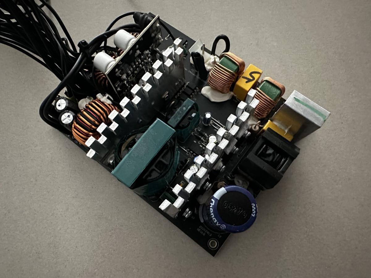
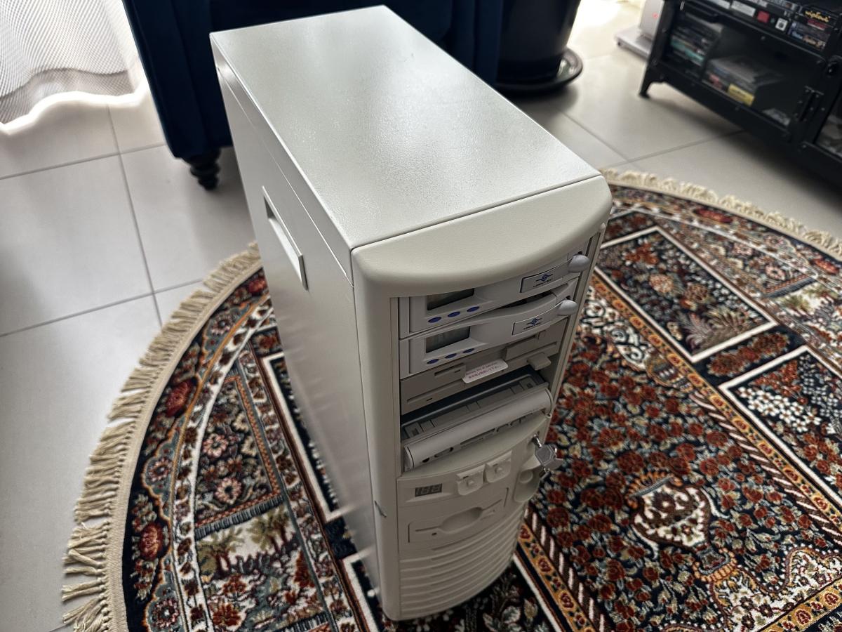
I’ll do so, as I’m going to be placing the guts of the new Power Supply into the Power Supply case which is in the chassis, like I did with the current Power Supply, as the Power Supply case in the chassis is not a standard form factor, and I also need it to interface with the Power Switch on the front of the chassis.
While waiting for the new power supply to arrive, I’ve removed the current one:
![]()
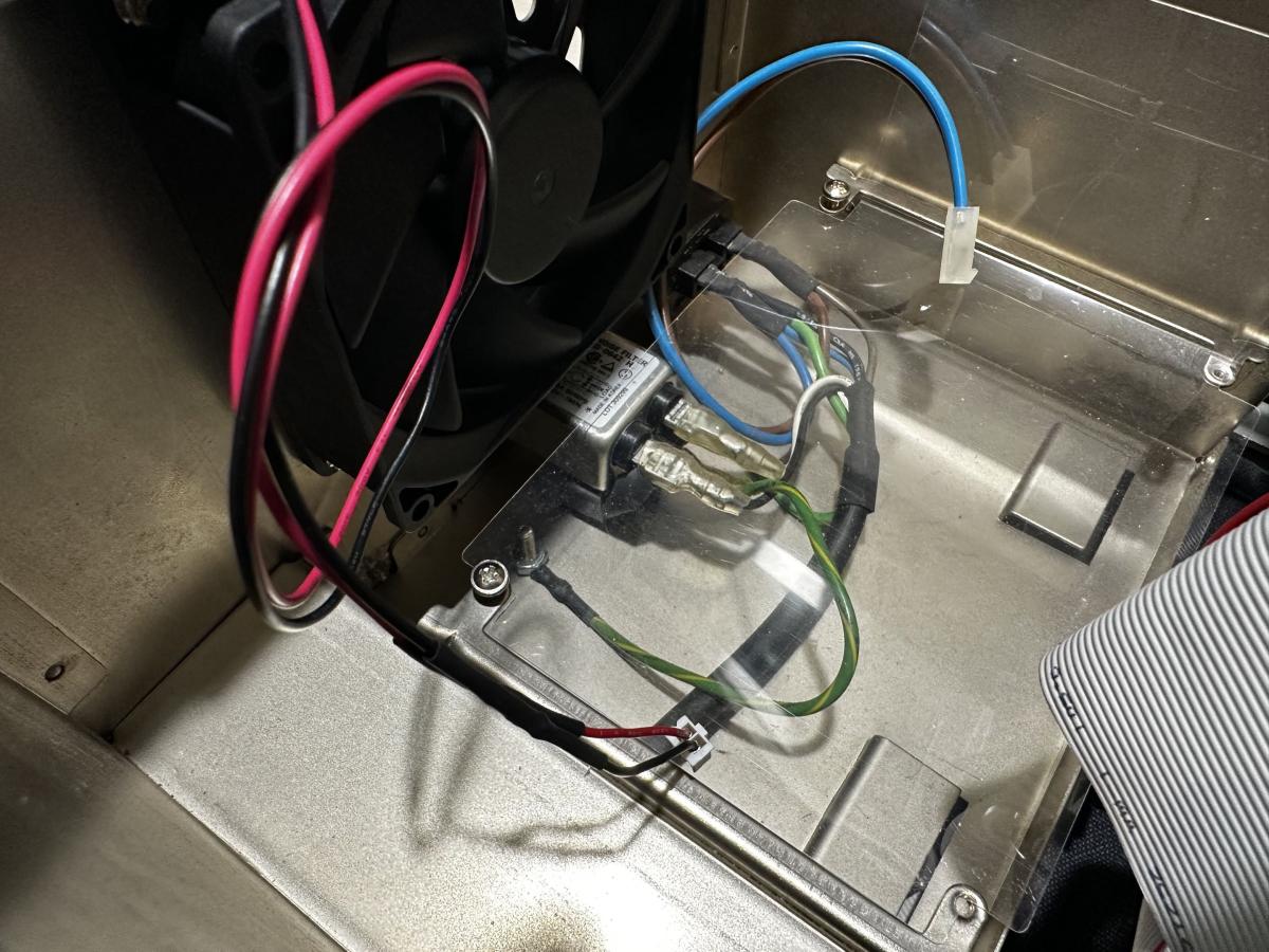
Luckily there’s already a line filter fitted, as the line filter arrangement in the new power supply’s pretty messy, so I’ll be able to discard it!
![]()
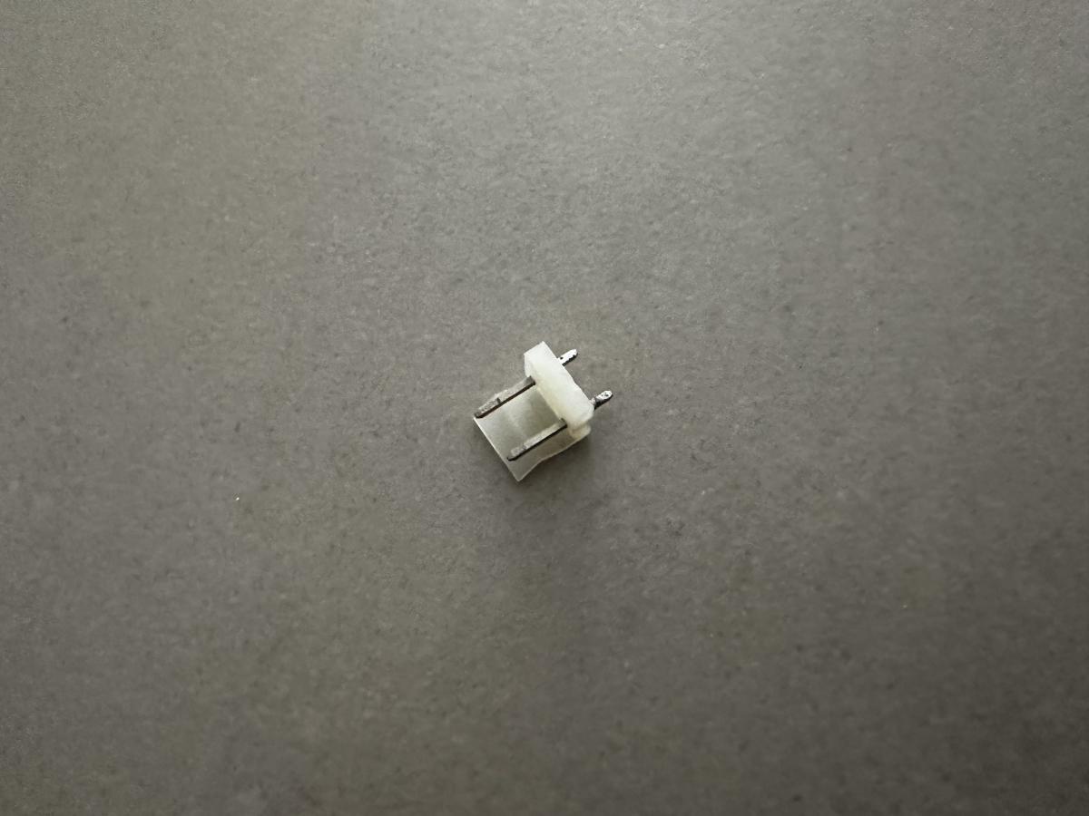
I’ll soldier this power coupling into the new power supplies board, allowing it to neatly plug into the existing wiring.
![]()
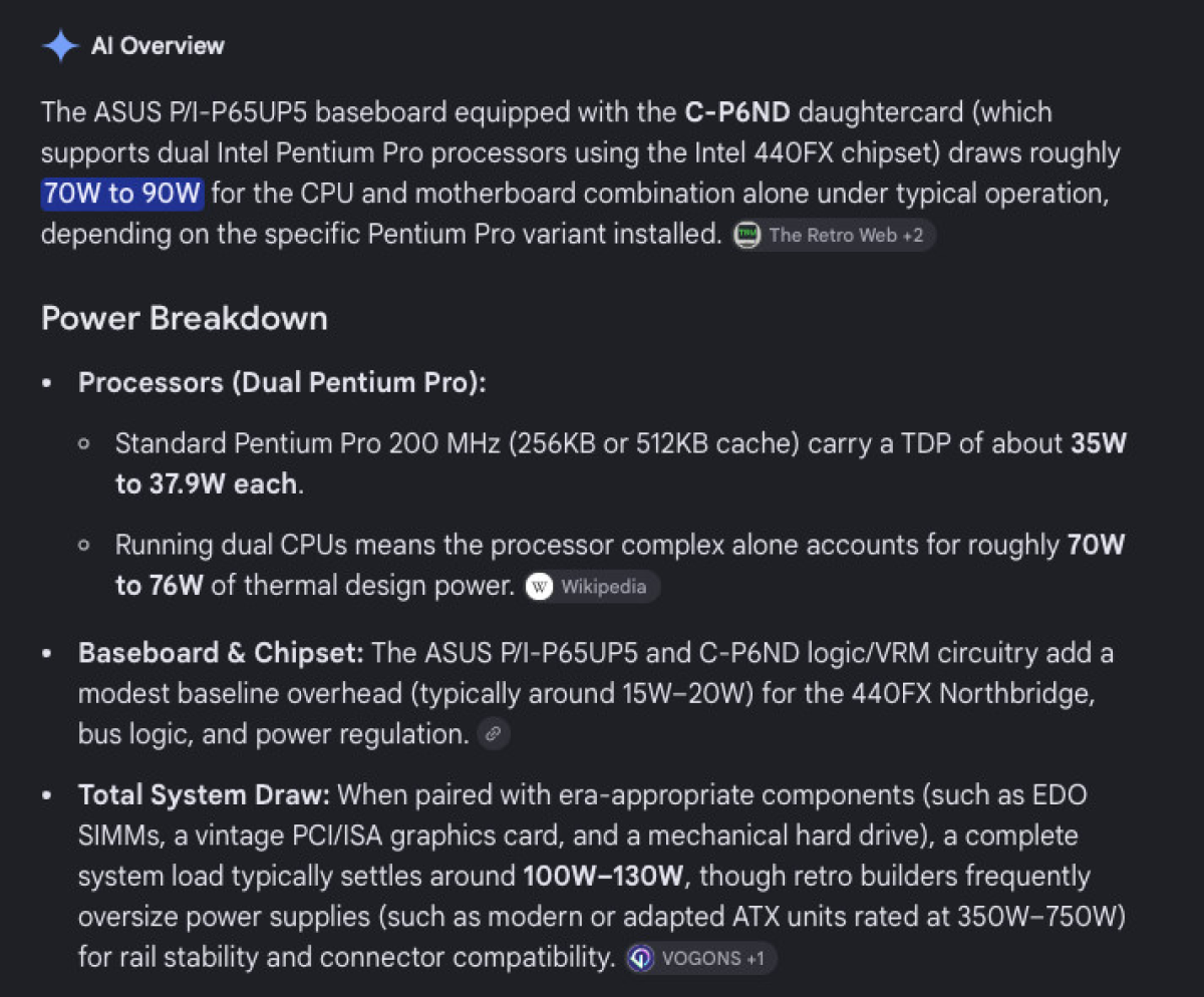
This gives you some idea as to how over budget I was power wise, using the Power Supply which could only supply 100W (20A) on the 5V rail:
![]()
I'm going to have to seriously lower my expectations here as to what I slot into this thing!
For now I'm thinking:
The Voodoo5 5500 PCI DVI for graphics, as it consumes 30W, but draws half of this power off the 12V rail.
I did consider using the Matrox Millennium II with a pair of Canopus Pure3D II's, but Voodoo2's consume 15W per card, therefore 30W in an SLI setup, with no relief from the 12V rail, plus you need to factor in the extra power consumption of the base 2D card, which is about an extra 5W. (So the Voodoo5's actually a better option here power wise.)
I won't be slotting in SCSI RAID card, but will instead use the 68-pin SCSI connector on the PCI-AS300 to run the System Drive and the 50-pin SCSI connector on the same card to run the SCSI CD-ROM's.
The PCI-AS300 also has a CREATIVE VIBRA sound card integrated into it, which will cover me sound card wise.
The only other card that I'm going to slot will be the 3Com EtherLink III 3C509B-C ISA RJ45 BNC AUI Combo LAN Card to give the system network.
Even with this slimmed down setup, I'm going to be pushing it power wise. (The extra CPU limits you as to what cards you can slot, while still remaining within the power budget of less than 150W on the 5V rail!)
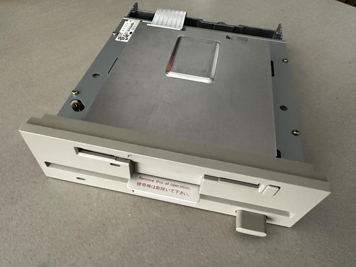
The TEAC combo floppy drive arrived today, and it’s in good shape!
![]()
![]()
I’m in the process of trying to negotiate shipping on a power supply which will give me 50A@5V. If I can get this for the system, then there will be no limit on the cards that I can slot!
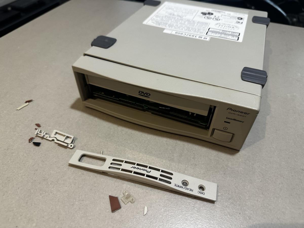
The DVD writer arrived completely broken! (I'm extremely unhappy about this, as I really wanted to include this drive in the system!)
![]()
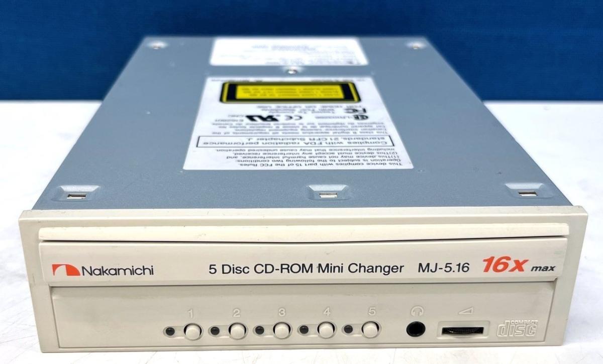
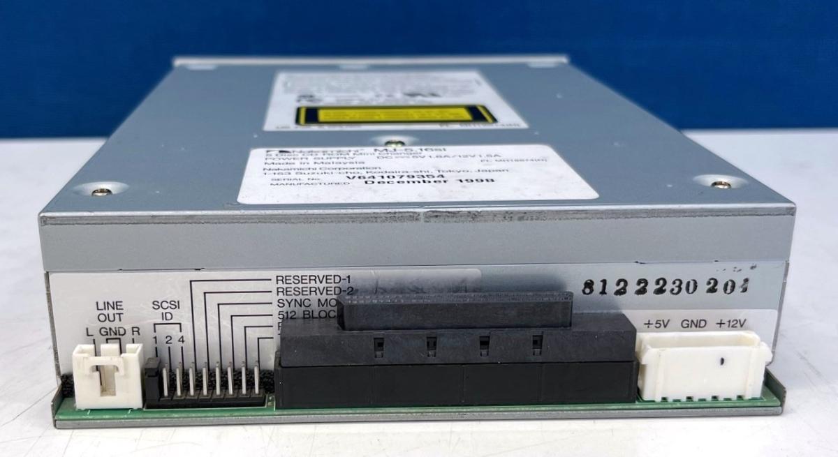
In the meantime I've purchased this Nakamichi 5 Disc CD-ROM Mini changer 16X drive as a replacement:
![]()
![]()
Hopefully this one arrives in one piece!
Irinikus wrote on Today, 12:35:In the meantime I've purchased this Nakamichi 5 Disc CD-ROM Mini changer 16X drive as a replacement: […]
In the meantime I've purchased this Nakamichi 5 Disc CD-ROM Mini changer 16X drive as a replacement:
Hopefully this one arrives in one piece!
Wow, that thing must be huuuuuuuuughely long? Or am I just out of imagination on how it would change the discs without moving them backwards in the enclosure?
If it's dual it's kind of cool ... 😎
--- GA586DX --- P2B-DS --- BP6 ---
Please use the "quote" option if asking questions to what I write - it will really up the chances of me noticing 😀
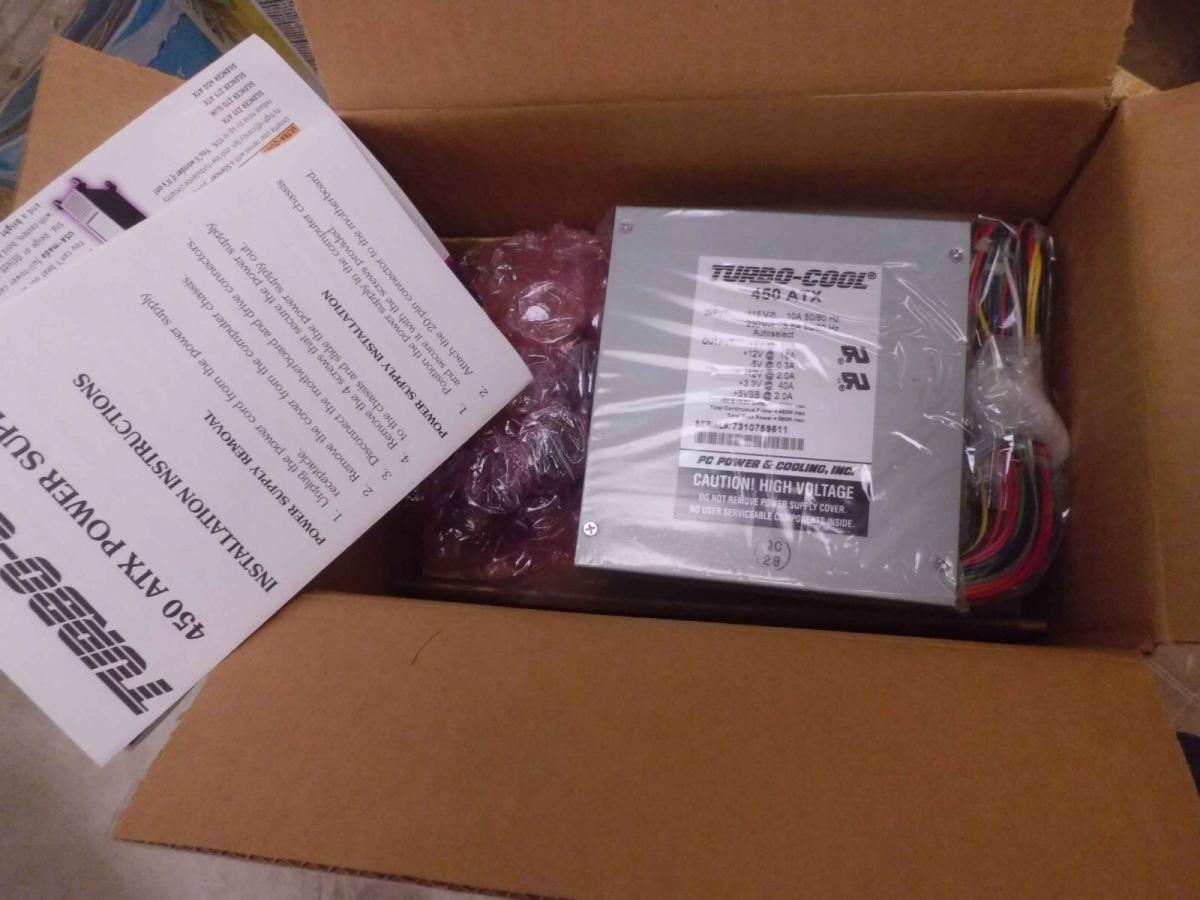
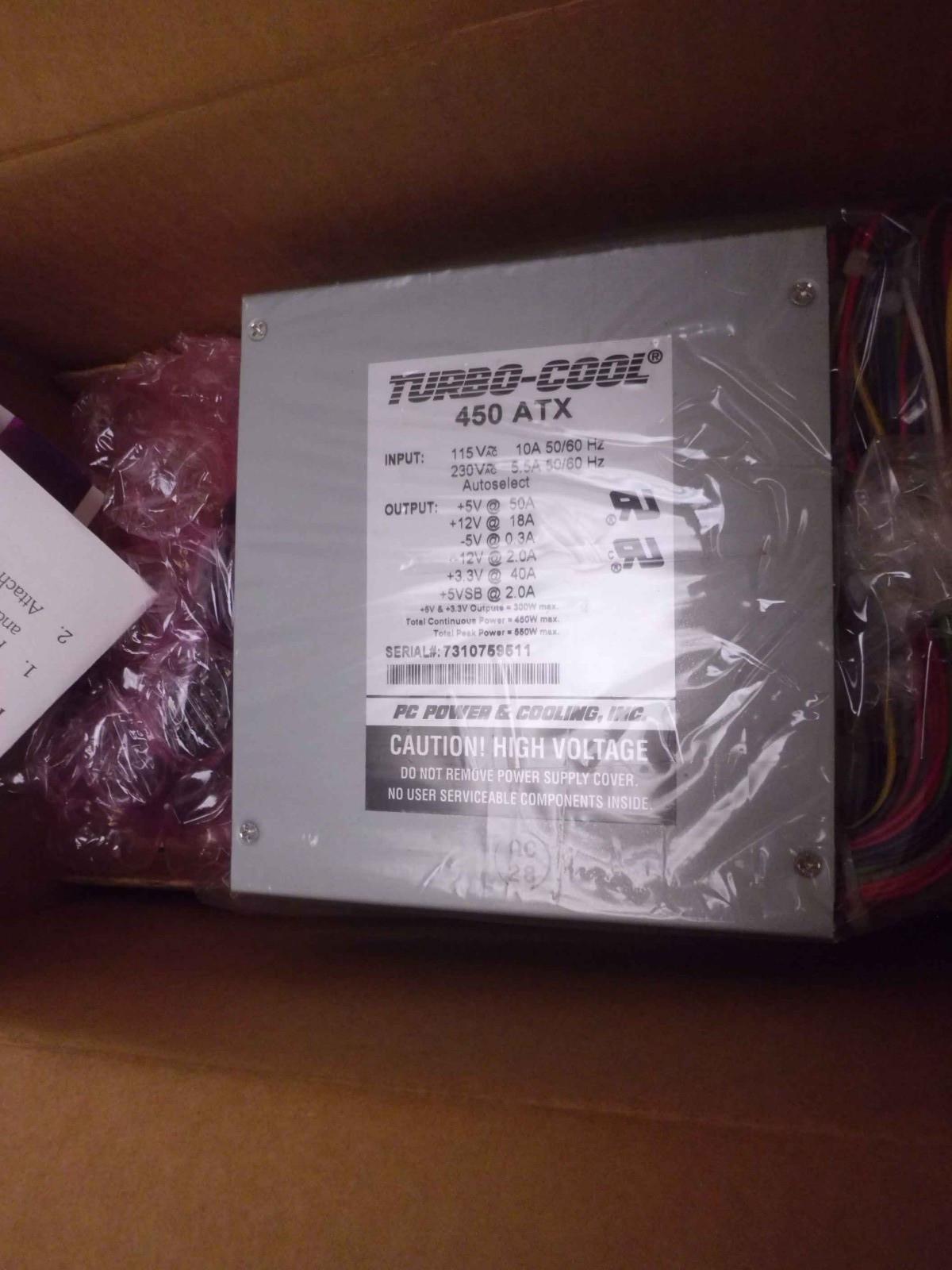
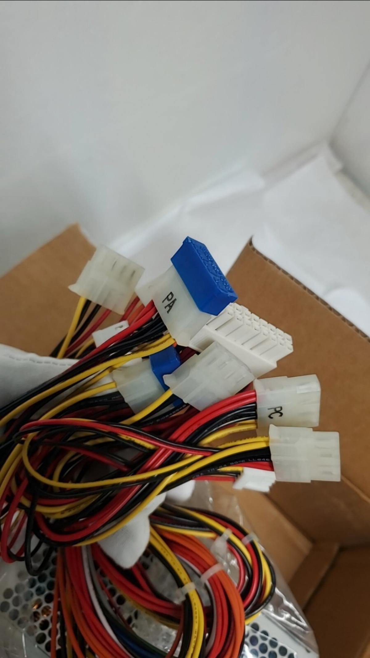
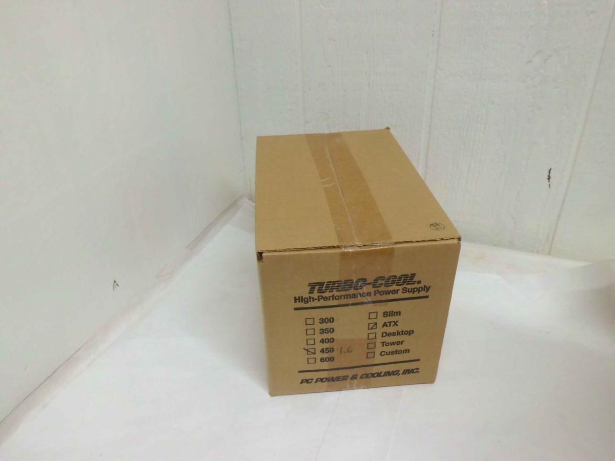
I've just ordered this NOS 450ATX PC POWER AND COOLING TURBO COOL 450 WATT ATX POWER SUPPLY for the system which supplies 5V@50A! (Now I wont have any limitation as to the cards that I can slot into this system! 😀 )
![]()
![]()
![]()
![]()
H3nrik V! wrote on Today, 13:21:Wow, that thing must be huuuuuuuuughely long? Or am I just out of imagination on how it would change the discs without moving them backwards in the enclosure?
It's actually a standard sized drive!
Irinikus wrote on Today, 13:32:I've just ordered this NOS 450ATX PC POWER AND COOLING TURBO COOL 450 WATT ATX POWER SUPPLY for the system which supplies 5V@50A! (Now I wont have any limitation as to the cards that I can slot into this system! 😀 )
you should check their cap! I also accquire two of them and both having bad caps