VOGONS


First post, by creepingnet

User metadata
Rank Oldbie
Rank
Oldbie

Ok, so last night I was upgrading my FIC 486-PVT motherboard to a AMD 486 DX4-100, and in the process, broke a pin off this weirdo thing......

IMG_20170214_011309831.jpg
Filename
IMG_20170214_011309831.jpg
File size
15.67 KiB
Views
2047 views
File comment
Jumper Network/0 Ohm 8p4R jumper network
File license
Fair use/fair dealing exception

I got it working for awhile by just sticking a piece of wire in the hole. At some point the machine was shifted, locked up, and now I can't get it to POST. I looked around online and found on this forum someone posted something similar regarding a 486-PIO3 board by the same manufacturer that these "RN16,RN17,RN18,RN19" thingies are actually a group of jumpers built into one unit.

pinout per conductivity test.jpg
Filename
pinout per conductivity test.jpg
File size
17.62 KiB
Views
2047 views
File comment
Continuity Test of B 000J
File license
Fair use/fair dealing exception

I'm starting to wonder if I should just work around it by using some staples or something put in to do the same job and if there are any issues caused by this, or if there is a source for these things. So far the closest thing I can find are SIP Resistor networks, which I don't think I want nor would they work.

I spent about 2 hours last night soldering pins on, and trying different things to no avail and the damn thing would not POST despite continuity between the pin and whatever else, it seems I may have just been latching onto the plastic packaging. This is with both the old Intel 486 DX2 and AMD DX4, not sure what's going on - I set the jumpers for both properly....so this is very odd. The board had no issues till I swapped out the CPU, and it ran GREAT for a few hours under the DX4 but then I went to change Audio inputs to reboot and it just would not POST again after that for whatever reason.

I'll say this, when I had that chip working, that thing was stupid-fast as soon as I enabled WriteBack Cache and all of the other cache settings.

~The Creeping Network~
My Youtube Channel - https://www.youtube.com/creepingnet
Creepingnet's World - https://creepingnet.neocities.org/
The Creeping Network Repo - https://www.geocities.ws/creepingnet2019/

Reply 1 of 18, by Tetrium

User metadata
Rank l33t++
Rank
l33t++

When you shifted the machine and the machine subsequently locked up, did the resistor also fell out?

I don't really know what could be the cause here. Superficially it seems several things are going wrong.

Sorry I can't be of any more help atm.

Whats missing in your collections?
My retro rigs (old topic)
Interesting Vogons threads (links to Vogonswiki)
Report spammers here!

Reply 2 of 18, by creepingnet

User metadata
Rank Oldbie
Rank
Oldbie
Tetrium wrote:

When you shifted the machine and the machine subsequently locked up, did the resistor also fell out?

I don't really know what could be the cause here. Superficially it seems several things are going wrong.

Sorry I can't be of any more help atm.

Nope, when the machine locked up, I'm assuming it's because the friction-fit makeshift pin I put on RN18 moved slightly, losing contact with the 0 ohm resistor SIP that is used to configure the CPU. I tried making it work some with the DX2-66.

I think tonight I'm going to try the staple-trick on it, maybe even make my own Duc-Tape cased SIP using that because finding a component like this has proven futile. I'm starting to think this was a custom-order Single Inline Package 0 Ohm resistor used by FIC to keep people from blowing up their board making errant jumper settings. I was mulling it over this morning some between buildings and I can't think the minimal resistance has any effect, after all, to my continuity tester, it's pretty much as good as a closed circuit between each pair of pins. A more elegant solution would be maybe to use a single row 8pin header and use jumpers to configure it, but I'd rather not stoop that far, I have the board out and laying around, so I might stay up tonight a little and build out my own little "staple jumper pack" and put it on there and see if that works with the DX2-66, and then after that, put the DX4 in, change the jumpers, and see if that works.

Talking to the guys on VCF, they mentioned soldering a pin on it after filing it off, that's tempting but last night I did have some problems, plus one of the other pins broke off, I'd rather just build something more robust and use that as soldering pins onto this thing using wire and solder has proven hard to impossible.

I'm just hoping there's not some other problem like the DX4 was faulty and fried, or that the system board had some other problem that came to light when the CPU was upgraded to a faster one with WriteBack Cache. Would be a shame if that CPU was a dud now b/c that thing performed shockingly well.

Maybe it's for the best though, if I can't get it going, maybe I'll just order another chip and wait, by then the Cache RAM and 128MB upgrade I got it will be in. Then I can just do it all one-fell-swoop.

~The Creeping Network~
My Youtube Channel - https://www.youtube.com/creepingnet
Creepingnet's World - https://creepingnet.neocities.org/
The Creeping Network Repo - https://www.geocities.ws/creepingnet2019/

Reply 3 of 18, by meljor

User metadata
Rank Oldbie
Rank
Oldbie

Maybe a bit ghetto but i would try and put a small screw in each hole so it would be a bit secure and then connect them with wrapping around some wire. Finishing the top of each 2 pins with wire with some electrical tape so all stays in place. Replacing the whole thing (unless there are some resistors in there?).

asus tx97-e, 233mmx, voodoo1, s3 virge ,sb16
asus p5a, k6-3+ @ 550mhz, voodoo2 12mb sli, gf2 gts, awe32
asus p3b-f, p3-700, voodoo3 3500TV agp, awe64
asus tusl2-c, p3-S 1,4ghz, voodoo5 5500, live!
asus a7n8x DL, barton cpu, 6800ultra, Voodoo3 pci, audigy1

Reply 4 of 18, by Ampera

User metadata
Rank Oldbie
Rank
Oldbie

I suggest you replace this. If you can prove it's a series of jumpers (And NOT a resistor array) then you can either solder wires across the holes, or get another series of jumpers. An idea is to see if you can get some headers and solder those in so you can just use standard jumpers.

Reply 5 of 18, by creepingnet

User metadata
Rank Oldbie
Rank
Oldbie
Ampera wrote:

I suggest you replace this. If you can prove it's a series of jumpers (And NOT a resistor array) then you can either solder wires across the holes, or get another series of jumpers. An idea is to see if you can get some headers and solder those in so you can just use standard jumpers.

I'll share how I came to this conclusion......let me reference this thread involving the FIC 486-PIO3 - FIC 486-PIO3 mobo - why's it so slow?

When I was first looking this part up a guy on VCF told me it was a "resistor network" - he was pretty much right on on that in a way - except each resistor in this non-bussed resistor network (or so it appears) measures 0 ohms resistance (0.0003Ω on a 200Ω Scale on my Multimeter to be exact). When I was testing the module, the VCF user said to hold the test probe to pin 1 and test all the other pins, thing is, only the pin next to it would give me the "beep" for continuity.

then I found that thread and THIS picture was posted by the user
jumper.jpg

Now here's my part - using the same sort of red-lines to show the continuity path between the pins, which is similar to a non-bussed 0 Ohm resistor
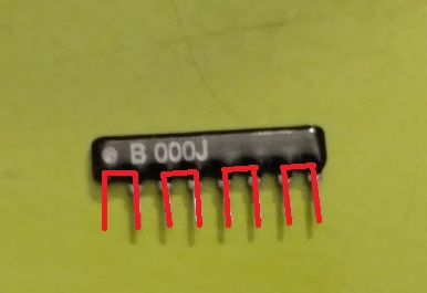
file.php?id=31581

I did some looking up on 0Ω Resistors and learned the following about them, they are used in manufacturing in place of a jumper or a plain wire when automated machinery is used. I could see FIC having some variant of Resistor network of 0Ω on multi-layer motherboards and components to allow a smaller footprint by tying different circuits through one, but I think in this case here, FIC was just trying to make sure people were not going to blow up their CPU/Motherbards with errant settings (kind of odd when you consider the variable voltage configurations).

I also did a resistance and continuity test on the part and the red lines over the legs display the path through it. I tried many other combinations, seems it's just 4 male jumpers in a plastic 8P4R Package - 8P4R standing for 8-pin 4 resistor package. Resistance reads on the 200Ω Scale at 0.0003Ω.

I tried the staple "trick" last night on it with both the DX2 and DX4 chips and neither worked, so I think something more is amiss now with this. Unless of course this component really was a resistor pack and something went awfully wrong turning it into a jumper - but I'm doubtful because all electronics experts (3 total) I've talked to say it's a 0Ω resistor network acting as a jumper, which to all of them seems strange.

It could be I had a bad CPU chip possibly, or maybe errant BIOS settings - I did change a BUNCH of BIOS settings on the board including changing the Memory speed and other speed settings to Turbo.

I won't rule it out being the DX4 chip possibly too, I bought what was a "gold scrapper special" - it had some bent pins, but it did work after straightening them and with some finagling on the first try. Maybe the faster RAM I have coming in could cure it too. Will have to check that out tonight when/if I have time to mess with it tonight. could also be Cache related because I enabled some Cache settings and may have errantly enabled the L2 cache which has been running for 3 years totally mis-configured with the wrong chips (a 16Kx8 Tag and 4 8Kx8 chips - I've got a 32Kx8 and 4 128Kx8 chips on the way to max it out at 512KB). I also glued the HSF onto it using superglue as a short term test, which seemed to be working quite well as the chip was running nice and fast right up till the machine locked up which was almost 4-5 hours After the superglue dried, and while I did see some seepage, it seems to have stayed away from the pins

when I run the DX2 chip, the chip gets warm like it should, I don't seem to feel the same effect from the DX4-100, but then the DX4 is 3 volts, and in a heatsink so I probably can't get as close to the source of heat. I did also have some problems with VLB cards popping out of their slots too at one point, so I'm not ruling that out, hopefully it's not a system bus failure issue - that could be a bit above my head to troubleshoot.

I did order my first Motherboard Testing card so maybe I can decode where it's getting, I know it's finding the keyboard and getting a power-good signal that much is for sure - hit the power switch, Keyboard lights blink, I'm just not getting any POST beeps or a screen. Also tried pulling the CMOS battery, but I might pull it for a longer time next time. Also tried a different ISA video card (OTI 077 VGA), no response from that card either, so it may not be BUS related. Reseated all RAM and tried starting without, still no beeps - but then I could have a flaw in my methods as I am using the audio passthrough on my SoundBlaster AWE64 Value to get any POST beeps from the system, and that's not the most reliable method.

Maybe if a POST redo does not work, maybe the darned thing just realized the errant Cache and will start working when I put the PROPER chips in - ie that 32Kx8 along with the 4 128Kx8 chips. That might be over a month though.

~The Creeping Network~
My Youtube Channel - https://www.youtube.com/creepingnet
Creepingnet's World - https://creepingnet.neocities.org/
The Creeping Network Repo - https://www.geocities.ws/creepingnet2019/

Reply 6 of 18, by creepingnet

User metadata
Rank Oldbie
Rank
Oldbie

Update - just to not leave you guys hanging - I figured out what was going on last night, got some time to figure it out.....

Turns out the DX4-100 burned itself out due to improper thermal work (my bad) - so I have another one on order. I put the DX2-66 back in and got it working. Seems my idea of using a certain adhesive for a heatsink compound did not work so well, it liquefied, and got into the socket, some cleaning of the 486 Socket with the .024w Ernie Ball guitar string dabbed in Acetone fixed it (this is how those hobbies intersect), plus some cleanup of the DX2-66 which had some kind of brown gunk on the bottom that I cleaned with an old toothbrush, water, and a dab of dish soap, and it booted right up. Also, here's some information for VOGONS if anyone else uses a FIC 486-PVT motherboard.....

RN16-RN19 are just there to identify the CPU's brand it seems. I left it in the AMD position, and my Intel 486 DX2-66 fired right up as a "80486 DX2-66 MHZ" chip instead of "Genuine Intel DX2 @66 MHz" or something like that. I'm leaving it there for now and not reassembling the machine until I have all of the parts in, which should take me over a month as I'm still waiting for the ISSI Cache RAM from China to get here (it's still in "posting" status since the 10th of February). The new 486 DX4 (exact same chip, AMD 486DX4 100SV8B - 8K L1 w/ WriteBack Cache) + the Heatsink I bought (a proper one) which I plan to retrofit my 3 pin motherboard powered fan to (this board is insanely modern for something so old in a lot of ways). The other CPU is getting cleaned up, might use it as a inlay on a Retro PC themed guitar or something.

I also found out something funny, I'd been running that Intel DX2-66 at a reduced voltage all this time - 3.3 Volts! I set it up at 5V, seems to POST a little faster now, maybe certain programs were going a bit slower than I remembered because the CPU was not getting enough juice.....I dunno. When the DX4 comes in, I'm moving the jumper back to the 3.0V position, and then the new heatsink is getting polished on the contact surface and a nice spread of some fresh thermal compound (the good stuff, I may even use a dab of my arctic silver on it) - and then that Fan is getting screwed on it. Not making the same mistake twice. But then that other chip may have had issues as it was listed as "gold Scrap" whereas the one I have coming in was listed as "tested, working" and has a return policy (and free shipping).

I also got my 128MB of RAM in, I'll be installing that tonight. What a relief that I won't have to buy a new Motherboard!

Attachments

  • IMG_20170215_205729469.jpg
    Filename
    IMG_20170215_205729469.jpg
    File size
    233.66 KiB
    Views
    1710 views
    File comment
    intel 486 DX2-66 CPU installed
    File license
    Fair use/fair dealing exception
  • IMG_20170215_205801456.jpg
    Filename
    IMG_20170215_205801456.jpg
    File size
    133.18 KiB
    Views
    1710 views
    File comment
    booting an Intel DX2 identified as an "AMD" LOL
    File license
    Fair use/fair dealing exception
  • IMG_20170215_234022601.jpg
    Filename
    IMG_20170215_234022601.jpg
    File size
    152.06 KiB
    Views
    1710 views
    File comment
    Staple Jumpers 2
    File license
    Fair use/fair dealing exception
  • IMG_20170215_234001815.jpg
    Filename
    IMG_20170215_234001815.jpg
    File size
    179.87 KiB
    Views
    1710 views
    File comment
    Staple 0Ohm Jumpers 1
    File license
    Fair use/fair dealing exception

~The Creeping Network~
My Youtube Channel - https://www.youtube.com/creepingnet
Creepingnet's World - https://creepingnet.neocities.org/
The Creeping Network Repo - https://www.geocities.ws/creepingnet2019/

Reply 7 of 18, by Tetrium

User metadata
Rank l33t++
Rank
l33t++

Personally I don't like AS, I've always preferred the white goo like MX-2. It's WAY easier to clean and for testing and doesn't seem to be any worse at all!

And for 486 stuff, TIM doesn't really seem to be critical in almost any way. It becomes more important when going to stuff that uses 100MHz FSB and anything Athlon or Coppermine isreally better off using TIM. Actually, running any earlier Athlon without any TIM is an easy way to fry them within the blink of an eye 😵

Whats missing in your collections?
My retro rigs (old topic)
Interesting Vogons threads (links to Vogonswiki)
Report spammers here!

Reply 8 of 18, by Matth79

User metadata
Rank Oldbie
Rank
Oldbie
Tetrium wrote:

Personally I don't like AS, I've always preferred the white goo like MX-2. It's WAY easier to clean and for testing and doesn't seem to be any worse at all!

And for 486 stuff, TIM doesn't really seem to be critical in almost any way. It becomes more important when going to stuff that uses 100MHz FSB and anything Athlon or Coppermine isreally better off using TIM. Actually, running any earlier Athlon without any TIM is an easy way to fry them within the blink of an eye 😵

Yep, TIM is critical for a CPU with no heatspreader, as any part of the chip not making thermal contact will burn - though that said, I did run an Athlon Thunderbird using my old power transistor "silicon grease" - only temporarily.

Reply 9 of 18, by creepingnet

User metadata
Rank Oldbie
Rank
Oldbie
Matth79 wrote:
Tetrium wrote:

Personally I don't like AS, I've always preferred the white goo like MX-2. It's WAY easier to clean and for testing and doesn't seem to be any worse at all!

And for 486 stuff, TIM doesn't really seem to be critical in almost any way. It becomes more important when going to stuff that uses 100MHz FSB and anything Athlon or Coppermine isreally better off using TIM. Actually, running any earlier Athlon without any TIM is an easy way to fry them within the blink of an eye 😵

Yep, TIM is critical for a CPU with no heatspreader, as any part of the chip not making thermal contact will burn - though that said, I did run an Athlon Thunderbird using my old power transistor "silicon grease" - only temporarily.

I don't have any of the old silicon grease stuff I used to buy at Radio Shack when they sold Socket 3 Heatsinks in the 2000. Just using what I have. I have a old tube of AS, and a bunch of tubes of leftover stuff from my I.T. career doing stuff for OEM's, I think I have some Toshiba stuff I bought when I rebuilt my laptop that's very similar to the white silicon stuff Rat Shack used to sell. Most of it is also just me being a tad OCD after having my first experience burning up a CPU. I've been working on computers seriously for over 15 years and have never once burned up a CPU until this year. I feel kind of...uh...silly about that because I should have known better.

~The Creeping Network~
My Youtube Channel - https://www.youtube.com/creepingnet
Creepingnet's World - https://creepingnet.neocities.org/
The Creeping Network Repo - https://www.geocities.ws/creepingnet2019/

Reply 10 of 18, by douglar

User metadata
Rank Oldbie
Rank
Oldbie

I think I have a similar problem with a FIC-486 -VIP.

I have a similar resister network--

Photo Mar 18, 7 20 05 PM.jpg
Filename
Photo Mar 18, 7 20 05 PM.jpg
File size
39.59 KiB
Views
1327 views
File license
Public domain

The manual seems to say: http://www.win3x.org/uh19/public/motherboard/ … anual/31937.pdf

  • No resistor network for 5V
  • JRN1 for AMD (3.45V ?)
  • JRN2 for Intel (3.3V)
  • JRN3 for Cyrix (3.6V ? )

I was running an AMD 5x86 on this board with the jumper in the intel position. One of the pins on the resistor network was a little short, but everything seemed OK.
I tried out a IBM DX4 100 CPU for a bit, but then I got a new BIOS for the board so I switched back to the AMD CPU to see if the write back cache worked.

Unfortunately I couldn't get the AMD 5x86 or the IBM DX4 100 to work any more, but I could still get 5V CPU's to work .

Looking at the board, I see 5V on the blue circles--

Photo Mar 18, 7 21 00 PM.jpg
Filename
Photo Mar 18, 7 21 00 PM.jpg
File size
443.65 KiB
Views
1327 views
File license
Public domain

The Vcc seems to be 5V regardless of where I put the resistor network. I tried adding some soldier to the short pin in case there was an open circuit, but no luck.

Did I break the resistor network? Are replacements available?

Reply 11 of 18, by majestyk

User metadata
Rank Oldbie
Rank
Oldbie

These resistor arrays / networks are in fact 4 or 5 zero ohms resistors aka "male jumpers".
They are no longer available so I produce them myself cutting the usual 2.54mm connectors into pieces and soldering little wires on top of them:

selfmade_array.JPG
Filename
selfmade_array.JPG
File size
87.41 KiB
Views
1291 views
File license
Fair use/fair dealing exception

They are fitting in the sockets safely and perfectly and can easily be placed in different positions unlike single wire-jumpers.
There are also 2.54mm connectors that have half the hight or less but they can not be grabbed as easily when pulling and inserting the array out of / in the socket.

The position of all relevant jumpers - and that´s not just the array - must be 100% correct to make the VRM supply the right voltage and to make the board start.
Here´s all you need:

http://cwcyrix.duckdns.org/ftp-archives/ftp.f … al/486/486-VIP/

I´m quite sure there´s no defect in the VRM circuit since this broadly used FIC VRM solution is very stable and reliable. There´s probably still one or more of the jumpers in the wrong position. Check very carefully stp by step.

Reply 12 of 18, by mkarcher

User metadata
Rank l33t
Rank
l33t
douglar wrote on 2021-03-20, 01:15:
The manual seems to say: http://www.win3x.org/uh19/public/motherboard/ … anual/31937.pdf […]
Show full quote

The manual seems to say: http://www.win3x.org/uh19/public/motherboard/ … anual/31937.pdf

  • No resistor network for 5V
  • JRN1 for AMD (3.45V ?)
  • JRN2 for Intel (3.3V)
  • JRN3 for Cyrix (3.6V ? )

The Vcc seems to be 5V regardless of where I put the resistor network. I tried adding some soldier to the short pin in case there was an open circuit, but no luck.

As already explained, the resistor network is a set of jumpers to be moved as a unit for your convenience. I don't have anything to add to that: They don't break easily (except if mechanically mishandle them), so that thing is most likely fine. If you have a short pin, just measure on the back side of the board whether that pair of pins the short pin belongs to is indeed making contact. If it is, no worries. If it is not, build the replacement as suggested.

But there is something to add: It is unlikely this network is controlling the VRM. These compound jumpers are usually used to configure the board for the type of pinout of the processor. While the basic 486 socket is standard, the extras (SMM and Write-Back L1 cache) were added in incompatible ways by different manufacturers. There are four commonly used pinouts for WB cache:

  • The Pentium Overdrive pinout, which has all pins that are somehow related to WB cache ("somehow related" includes SRESET, a soft reset that doesn't invalidate or flush the L1 cache) on the new outer range of pins
  • The classic Cyrix WB cache pinout (Write-back cache is present in all Cx486DX processors, no matter whether they have a Write-Back logo on them).
  • The classic AMD WB cache / multiplicator selection pinout
  • The Intel Enhanced 486DX4 cache / multiplicator selection pinout

Be aware that both AMD and Cyrix switched over to the Intel pinout at some time. As a rule of thumb, 5V cyrix processors use the Cyrix pinout, and low-voltage (3.3 to 4V) Cyrix processors use the Intel DX4 pinout (Cyrix has a "standard pinout" marking on the first Cyrix processors using the Intel pinout). I have seen AMD DX4 processors with both kinds of pinouts. AMD 5x86 are only available in Intel DX4 pinout.

What this resistor network / jumper array is most likely doing: It connects different pins of the standard 486 socket pins with the outer row, so the classic Cyrix pinout, the AMD pinout or the Intel DX4 pinout is made to be use the same pins as the Pentium Overdrive pinout. The fine details about the bus protocol is handled by the BIOS setting up the chipset in the correct way. So it is not surprising that this resistor network does not change the voltage of the processor. And if you try to use modern processors, like the Cyrix 5x86 or the AMD 5x86, this network most likely needs to be in the Intel position, not the AMD or Cyrix position!

Reply 13 of 18, by douglar

User metadata
Rank Oldbie
Rank
Oldbie
mkarcher wrote on 2021-03-20, 10:12:

What this resistor network / jumper array is most likely doing: It connects different pins of the standard 486 socket pins with the outer row, so the classic Cyrix pinout, the AMD pinout or the Intel DX4 pinout is made to be use the same pins as the Pentium Overdrive pinout. The fine details about the bus protocol is handled by the BIOS setting up the chipset in the correct way. So it is not surprising that this resistor network does not change the voltage of the processor. And if you try to use modern processors, like the Cyrix 5x86 or the AMD 5x86, this network most likely needs to be in the Intel position, not the AMD or Cyrix position!

OK, thanks for the old docs. They match up with the PDF here: http://www.win3x.org/uh19/motherboard/show/2409
I took a picture of the jumpers when they worked so I got that going for me: http://www.win3x.org/uh19/public/motherboard/ … 9b280146946.jpg

Checking the Jumper network, I see that these pins are connected: 1&2, 3&4, 5&6, 7&8 so it's reversible, and it all looks good. I'll flip the board over and make sure they are connecting to the JRN socket later today.

Maybe I have a broken jumper somewhere that isn't making a good connection. I'll review.

Still concerned that I was seeing 5v on Vcc in the socket. There is no voltage select jumper other than maybe the JRN jumper network.

Any chance this is a voltage autodetect motherboard? Connect pin S4 to ground?

Reply 14 of 18, by mkarcher

User metadata
Rank l33t
Rank
l33t
douglar wrote on 2021-03-20, 13:59:

Any chance this is a voltage autodetect motherboard? Connect pin S4 to ground?

Quite possible. Q3 is an N-Channel MOSFET. This component can work like an electronically controlled jumper that conducts quite high power. Components like this are commonly used on auto-detect mainboards to bypass the 3.45V regulator if a 5V CPU is inserted. If the thick trace emerging from Q3 on the component size is connect with VCC of the processor, and the pin at the other end of Q3 is connected to +12V via a resistor, and the central pin of Q3 is directly connected to +5V, it is extremely likely an autodetect mainboard.

Reply 15 of 18, by majestyk

User metadata
Rank Oldbie
Rank
Oldbie

Most / all of the FIC onboard VRMs work the same.
IF the high current MOSFET Q3 (Q2 on some boards) is present, 5V CPUs are autodetected by checking the CPU´s "5V CPU present" pin.
IF Q3 / Q2 is not populated, the 16-pin Jumperblock is present instead. 5V CPUs have to be jumpered manually then by placing 2 Jumpers on each end of the block. (All jumpers setting 3V, 3.3V, 3,45 or 3.6V are overruled in this case.)
It´s the same 16-pin block, where an external FIC VRM-board can be plugged in if there´s no VRM onboard at all.

The hardware is working billiantly on all boards, but jumpering is quite a mess and differs between mainboard models. To make things even worse there are some mistakes in the manuals or manuals did not address CPUs that were released later, while they were supported by BIOS updates.
Once you find the right configuration everything is perfect. But it´s just for this very CPU and this very mainboard.
Many FIC 486 boards are running with slightly faulty jumperings without the owners even noticing.
Back in the days - although this was daily business - it was hard work (and a lot of swearing) until everything was set up perfectly.

Reply 16 of 18, by douglar

User metadata
Rank Oldbie
Rank
Oldbie
mkarcher wrote on 2021-03-20, 16:39:

Quite possible. Q3 is an N-Channel MOSFET. This component can work like an electronically controlled jumper that conducts quite high power. Components like this are commonly used on auto-detect mainboards to bypass the 3.45V regulator if a 5V CPU is inserted. If the thick trace emerging from Q3 on the component size is connect with VCC of the processor, and the pin at the other end of Q3 is connected to +12V via a resistor, and the central pin of Q3 is directly connected to +5V, it is extremely likely an autodetect mainboard.

Thanks for your help. Looking at the current on Q3, it has a Vcc connect and a +12V and the center pin is +5V.

How can I trigger the voltage detect to 3.3V to see if it is working? Would I just connect a ground to the VoltDet pin in the socket?

Reply 17 of 18, by mkarcher

User metadata
Rank l33t
Rank
l33t
douglar wrote on 2021-03-20, 21:47:
mkarcher wrote on 2021-03-20, 16:39:

Quite possible. Q3 is an N-Channel MOSFET. This component can work like an electronically controlled jumper that conducts quite high power. Components like this are commonly used on auto-detect mainboards to bypass the 3.45V regulator if a 5V CPU is inserted. If the thick trace emerging from Q3 on the component size is connect with VCC of the processor, and the pin at the other end of Q3 is connected to +12V via a resistor, and the central pin of Q3 is directly connected to +5V, it is extremely likely an autodetect mainboard.

Thanks for your help. Looking at the current on Q3, it has a Vcc connect and a +12V and the center pin is +5V.

How can I trigger the voltage detect to 3.3V to see if it is working? Would I just connect a ground to the VoltDet pin in the socket?

Exactly. Bridge the VolDet pin to ground, and this should shut off Q3, so the regulator automatically kicks in and delivers 3.3 or (more likely) 3.45 volts. I don't know how strong you need to pull VolDet down, but likely 100 Ohms would also do instead of a wire. Using a 100 Ohm resistor is safer in case you hit the wrong pin and accidentally try to pull down VCC instead of voldet.

Reply 18 of 18, by douglar

User metadata
Rank Oldbie
Rank
Oldbie

Thanks for the assistance. The board is a voltage autodetect board, as you guys predicted. Turns out that the AMD CPU is most likely dead, which makes me sad because it was an “ADZ” chip that didnt need a fan. Well, in hindsight, maybe it could have benefitted from a fan.

Board seems to be working OK with the 4.27gn2a bios, but the CPU identification strings are still not so good.

Edit- Turns out that the heatsink mount was preventing the chip from going in all the way. Different heat sink mount, AMD DX133 is back in action.