Ampera wrote:I suggest you replace this. If you can prove it's a series of jumpers (And NOT a resistor array) then you can either solder wires across the holes, or get another series of jumpers. An idea is to see if you can get some headers and solder those in so you can just use standard jumpers.
I'll share how I came to this conclusion......let me reference this thread involving the FIC 486-PIO3 - FIC 486-PIO3 mobo - why's it so slow?
When I was first looking this part up a guy on VCF told me it was a "resistor network" - he was pretty much right on on that in a way - except each resistor in this non-bussed resistor network (or so it appears) measures 0 ohms resistance (0.0003Ω on a 200Ω Scale on my Multimeter to be exact). When I was testing the module, the VCF user said to hold the test probe to pin 1 and test all the other pins, thing is, only the pin next to it would give me the "beep" for continuity.
then I found that thread and THIS picture was posted by the user

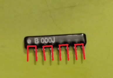
Now here's my part - using the same sort of red-lines to show the continuity path between the pins, which is similar to a non-bussed 0 Ohm resistor
I did some looking up on 0Ω Resistors and learned the following about them, they are used in manufacturing in place of a jumper or a plain wire when automated machinery is used. I could see FIC having some variant of Resistor network of 0Ω on multi-layer motherboards and components to allow a smaller footprint by tying different circuits through one, but I think in this case here, FIC was just trying to make sure people were not going to blow up their CPU/Motherbards with errant settings (kind of odd when you consider the variable voltage configurations).
I also did a resistance and continuity test on the part and the red lines over the legs display the path through it. I tried many other combinations, seems it's just 4 male jumpers in a plastic 8P4R Package - 8P4R standing for 8-pin 4 resistor package. Resistance reads on the 200Ω Scale at 0.0003Ω.
I tried the staple "trick" last night on it with both the DX2 and DX4 chips and neither worked, so I think something more is amiss now with this. Unless of course this component really was a resistor pack and something went awfully wrong turning it into a jumper - but I'm doubtful because all electronics experts (3 total) I've talked to say it's a 0Ω resistor network acting as a jumper, which to all of them seems strange.
It could be I had a bad CPU chip possibly, or maybe errant BIOS settings - I did change a BUNCH of BIOS settings on the board including changing the Memory speed and other speed settings to Turbo.
I won't rule it out being the DX4 chip possibly too, I bought what was a "gold scrapper special" - it had some bent pins, but it did work after straightening them and with some finagling on the first try. Maybe the faster RAM I have coming in could cure it too. Will have to check that out tonight when/if I have time to mess with it tonight. could also be Cache related because I enabled some Cache settings and may have errantly enabled the L2 cache which has been running for 3 years totally mis-configured with the wrong chips (a 16Kx8 Tag and 4 8Kx8 chips - I've got a 32Kx8 and 4 128Kx8 chips on the way to max it out at 512KB). I also glued the HSF onto it using superglue as a short term test, which seemed to be working quite well as the chip was running nice and fast right up till the machine locked up which was almost 4-5 hours After the superglue dried, and while I did see some seepage, it seems to have stayed away from the pins
when I run the DX2 chip, the chip gets warm like it should, I don't seem to feel the same effect from the DX4-100, but then the DX4 is 3 volts, and in a heatsink so I probably can't get as close to the source of heat. I did also have some problems with VLB cards popping out of their slots too at one point, so I'm not ruling that out, hopefully it's not a system bus failure issue - that could be a bit above my head to troubleshoot.
I did order my first Motherboard Testing card so maybe I can decode where it's getting, I know it's finding the keyboard and getting a power-good signal that much is for sure - hit the power switch, Keyboard lights blink, I'm just not getting any POST beeps or a screen. Also tried pulling the CMOS battery, but I might pull it for a longer time next time. Also tried a different ISA video card (OTI 077 VGA), no response from that card either, so it may not be BUS related. Reseated all RAM and tried starting without, still no beeps - but then I could have a flaw in my methods as I am using the audio passthrough on my SoundBlaster AWE64 Value to get any POST beeps from the system, and that's not the most reliable method.
Maybe if a POST redo does not work, maybe the darned thing just realized the errant Cache and will start working when I put the PROPER chips in - ie that 32Kx8 along with the 4 128Kx8 chips. That might be over a month though.


