VOGONS


First post, by Whiskey

User metadata
Rank Member
Rank
Member

Hi Vogons,

So I bought one of these Gameport MIDI cables with Joystick pass-through off ebay, I did a little research and tried to buy what looked like a good quality cable (about all in all £15).

After reading about people having a bad time with cheapo cables I decided to take it apart and check out the wiring, which is why im writing this. While the soldering is acceptable, the wires are clean and even the connector shielding is grounded correctly I'm concerned its just missing the electronics required to function correctly. There are zero resistors... I'm not sure if this is normal as the impression I got from the MIDI Joystick breakout thread was there should be at least some inline resistors for the cable to do its job properly.

Anyway I'd like some second opinions before I go using a would-be duff cable and destroy some thing I care about.
Link to photos and a pin-out of the cable. https://imgur.com/a/i2kSUxB

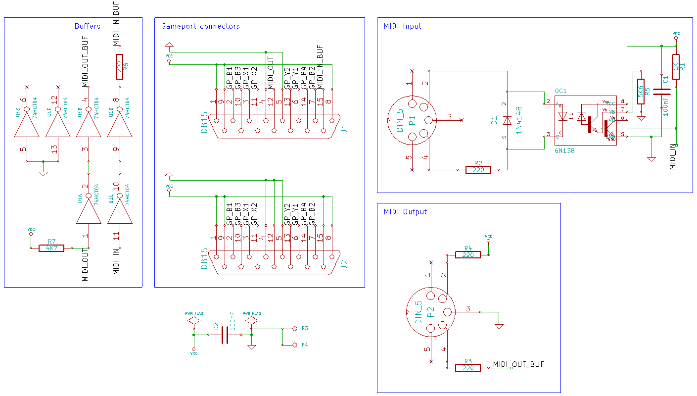
Here is the diagram keropi posted on the aforementioned thread for reference with the resistors inline with pins 4 and 5 (pins 2&4 on my diagram).
tzvAwcJl.png

Thanks in advance, W.

I stream retro games every wednesday here & I dump the recordings here

Reply 1 of 13, by JudgeMonroe

User metadata
Rank Member
Rank
Member

I would not use it with any gear I cared about. Get a refund. These cheap fake cables are legion on ebay.

This cannot pass through any joystick signals, so it's a pointless cost increase to even have included it.

The IC is meant to be a buffer between the MIDI device and the sound card, sort of like a fuse. In a real circuit, the MIDI OUT uses a hex inverter as a buffer, and the MIDI IN uses an optoisolator. Without these components, MIDI OUT will probably "work" but without a safety net. MIDI IN should not be used without the optoisolator.

Reply 2 of 13, by Srandista

User metadata
Rank Oldbie
Rank
Oldbie

You can't even be sure, if it will work with MIDI gear correctly at all.

Issues connecting a Roland SC-55 to an old 486

Socket 775 - ASRock 4CoreDual-VSTA, Pentium E6500K, 4GB RAM, Radeon 9800XT, ESS Solo-1, Win 98/XP
Socket A - Chaintech CT-7AIA, AMD Athlon XP 2400+, 1GB RAM, Radeon 9600XT, ESS ES1869F, Win 98

Reply 3 of 13, by Whiskey

User metadata
Rank Member
Rank
Member

So is it possible for me to buy the right components and modify this cable so it follows the correct midi specs?

I found this diagram on the thread Srandista posted, but my electronic diagram reading skills are not so good.
Small warm up project - Gameport/MIDI box schematic by user alexanrs
user keropi also posted some useful diagrams here Good schematic for simple joystick->midi-out adapter?

midicablediagram2.png

Any advice on creating a parts list and clear assembly instructions would be very appreciated.
Thanks W.

Edit: Here is what I have worked out so far:

1x 74HCT04 (Hex Inverter on this diagram) or possibly the more readily available 74LS00 (quad 2-input nand gate on the one in the first post) 74HCT04 allows the joystick to work simultaneously I believe.
1x 6N138 (optoisolator)
1x1N4148 (Small Signal Diode)
1x 4k7 ohm resistor
1x 200 ohm resistor
3x 220 ohm resistor
1x 5k6 ohm resistor
1x 1k ohm resistor
2x 0.1uF / 100nF Capacitor (good catch imi)

Last edited by Whiskey on 2019-09-05, 15:29. Edited 2 times in total.

I stream retro games every wednesday here & I dump the recordings here

Reply 4 of 13, by imi

User metadata
Rank l33t
Rank
l33t

C1 and C2 says 100nF, those are usually all rated for high voltages anyways.

I got that same exact cable from china btw, it was pretty much the only one that was in stock and looked decent enough, I also opened it up as soon as I got it and got disappointed, at least the cables and connectors seem to be pretty decent quality... I will fix mine as well 😀

Last edited by imi on 2019-09-05, 14:49. Edited 1 time in total.

Reply 5 of 13, by Whiskey

User metadata
Rank Member
Rank
Member

I'm setting up a 'clearer' diagram which I'll post soon, please chime in with any alterations/corrections or just anything you want to change or add. This is the first real electronics project I've done that wasn't replacing caps or following kit instructions. Cheers imi

I stream retro games every wednesday here & I dump the recordings here

Reply 6 of 13, by Whiskey

User metadata
Rank Member
Rank
Member

So I tried to get a hold of alexanrs here on vogons but I've had no reply and he hasn't been on in 2 years, so I've given KiCAD a go to re-create his design to the best of my ability without just copying it.

Here's what I've managed, if anyone with PCB CAD knowledge could proof it for me that would be great.
Nothing fancy, used auto-routing and component footprints from Mouser.co.uk product listings for the components used.
I'm very new at this so It might not even be correct, I had difficulty with the pin numbering and the footprints of the components I could find available to buy online.

Top.png
Filename
Top.png
File size
71.22 KiB
Views
2576 views
File license
Fair use/fair dealing exception
Bottom.png
Filename
Bottom.png
File size
88.67 KiB
Views
2576 views
File license
Fair use/fair dealing exception
diagramNEW.png
Filename
diagramNEW.png
File size
81.35 KiB
Views
2576 views
File license
Fair use/fair dealing exception
Midi Board-Top1.png
Filename
Midi Board-Top1.png
File size
59.59 KiB
Views
2576 views
File license
Fair use/fair dealing exception
Midi Board-Bot2.png
Filename
Midi Board-Bot2.png
File size
81.92 KiB
Views
2576 views
File license
Fair use/fair dealing exception

I stream retro games every wednesday here & I dump the recordings here

Reply 8 of 13, by Whiskey

User metadata
Rank Member
Rank
Member

Hi Muon, I didn't get any further than this as I lacked the know how.

I ended up finding a new old stock Creative MIDI joystick splitter cable from a music shop and kind of gave up as serdashop make the DB15MIDI for cheap which is basically the same without the joystick pass through.

I stream retro games every wednesday here & I dump the recordings here

Reply 9 of 13, by Mu0n

User metadata
Rank Member
Rank
Member
Whiskey wrote on 2021-04-08, 15:42:

Hi Muon, I didn't get any further than this as I lacked the know how.

I ended up finding a new old stock Creative MIDI joystick splitter cable from a music shop and kind of gave up as serdashop make the DB15MIDI for cheap which is basically the same without the joystick pass through.

Thanks for replying!
I really liked your no-compromise solution. I just made a thread about my cable woes here: Bought a gameport joystick/MIDI cable splitter from aliexpress, had to redo
While the DB15MIDI is great (bought one last year), my 486 only has one gameport so I can't also have a joystick at the same time, which is a bummer for Wing Commander 1&2.

If I stay frugal, I mostly need 1 joystick at once (2 buttons at most) and MIDI out. It would be nice to have all the options, of course, but at a certain point, learning how to design PCBs and the whole fab ordering and such would get me diminishing returns. My cable will do for now.

1Bit Fever Dreams: https://www.youtube.com/channel/UC9YYXWX1SxBhh1YB-feIPPw
DOS Fever Dreams: https://www.youtube.com/channel/UCIUn0Dp6PM8DBTF-5g0nvcw

Reply 10 of 13, by bassybeats

User metadata
Rank Newbie
Rank
Newbie
Whiskey wrote on 2019-09-09, 16:40:
So I tried to get a hold of alexanrs here on vogons but I've had no reply and he hasn't been on in 2 years, so I've given KiCAD […]
Show full quote

So I tried to get a hold of alexanrs here on vogons but I've had no reply and he hasn't been on in 2 years, so I've given KiCAD a go to re-create his design to the best of my ability without just copying it.

Here's what I've managed, if anyone with PCB CAD knowledge could proof it for me that would be great.
Nothing fancy, used auto-routing and component footprints from Mouser.co.uk product listings for the components used.
I'm very new at this so It might not even be correct, I had difficulty with the pin numbering and the footprints of the components I could find available to buy online.

Top.png
Bottom.png
diagramNEW.png
Midi Board-Top1.png
Midi Board-Bot2.png

Hey so do you have the files available if I wanted to try get one made at JLCPCB?

Reply 11 of 13, by Whiskey

User metadata
Rank Member
Rank
Member

@bassybeats Hi I'm afraid I never went any further with this project as I just didn't know enough about PCB design to know if it was correct, let alone work. There's also a chance I've lost the design files when a SSD died., I will however have a search through backups if you are interested in taking the design and seeing if you can achieve what I did not.

W.

I stream retro games every wednesday here & I dump the recordings here

Reply 12 of 13, by TOMMY_THE_DOG

User metadata
Rank Newbie
Rank
Newbie

You guys are making this harder than it has to be...
They sell old-stock Casio-branded cables on eBay for $20 all day long.
https://www.ebay.com/itm/224873650217?epid=12 … dIAAOSwvgFhW2sy

I have one of these and it works great. I use it for my gamepad and to output MIDI to my SoundCanvas (SC-880), and it does a great job of doing that. I can use the gamepad at the same time as the MIDI is being output, and there is also a breakout for a second player. I have not used it in 2-player mode. But the cable is cheap, it works great, and it is from a major name brand. I have tested it with a Vortex 2, a Yamaha YMF744, and an integrated ESS-Solo1. No issues. I use the hell out of this cable.

Reply 13 of 13, by Mu0n

User metadata
Rank Member
Rank
Member

I've gone and done my own thing on proto boards by now, complete with opto-isolators, diodes and such. I needed one for my mt32-pi recreation and another just to play games at work.

1Bit Fever Dreams: https://www.youtube.com/channel/UC9YYXWX1SxBhh1YB-feIPPw
DOS Fever Dreams: https://www.youtube.com/channel/UCIUn0Dp6PM8DBTF-5g0nvcw