First post, by Predator99
Predator99
Offline
Rank
l33t
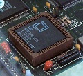
Dont have time to start this project now but would like to prepare: Does anybody own this card? Mine is missing some components. Maybe its possibble to guess the caps but for the "Q1" (red-green circle) I have no idea what to put in?
I think the cable can also be assembled from an IDE-cable and a socket. Pinout should be clear after identifying GND and VCC.
Already got the 8086 from China and found a reference photo, but I cannot read any value.
Thanks!