First post, by MaverickUK

- Rank
- Newbie
The HDD Clicker sounds like a fantastic idea.
However it got it thinking, would it be possible to simulate more of the experience? Such as the sound of a mechanical hard drive spinning up and more realistic access sounds?
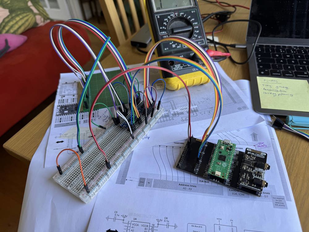
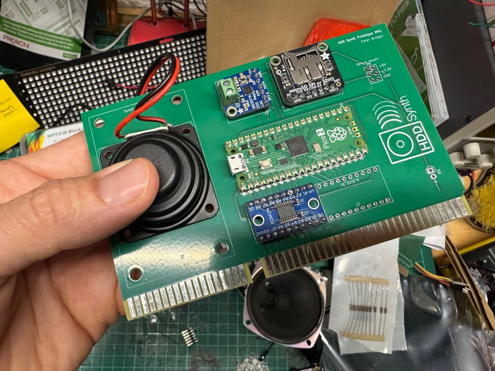
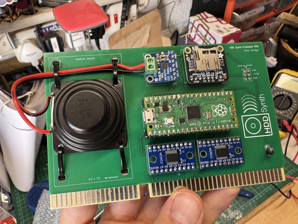
After wrangling some CircuitPython code with a spare Raspberry Pi Pico & Pico Audio I had my answer:
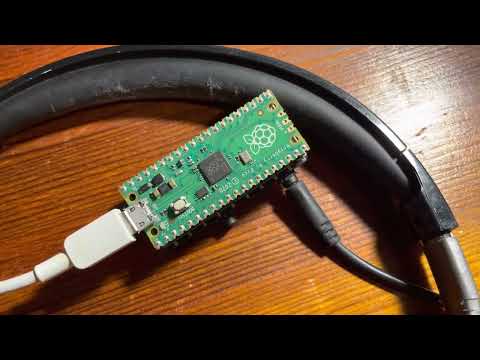
YouTube video of the device in action
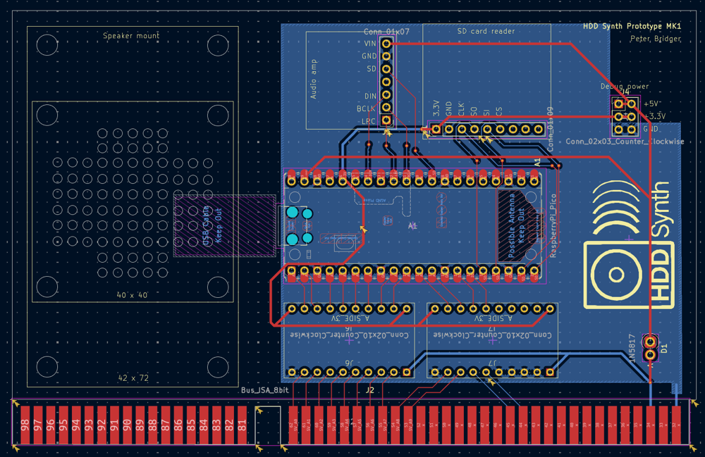
How it works
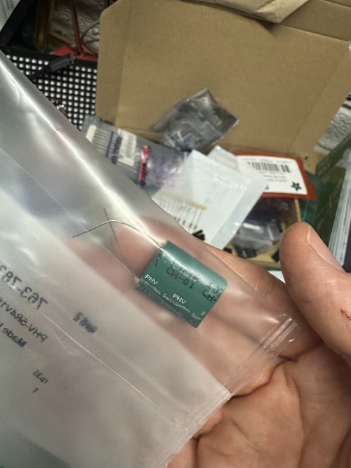
There are three WAV files on the Raspberry Pi Pico
- Spin up
- Idling
- Disk access
When the Raspberry Pi Pico retrieve power it starts by playing the spin up WAV file. Once this is complete it will continuously loop the idling WAV file. When
HDD activity is detected it then switches to looping the disk access WAV file.
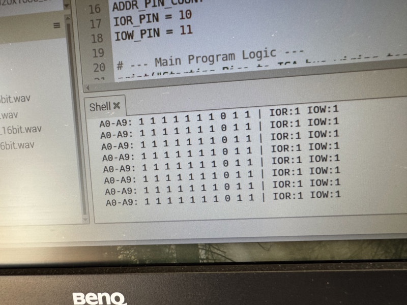
HDD activity is detected by using the analogue inputs on the Pico, so that when a PCs HDD LED lights up it detects the voltage and will then play the disk access sound.
I have also programmed it to output 3.3V on another set of Pico pins when HDD access is detected, which can be used to connect up to the PCs HDD LED should the original connection be disconnected
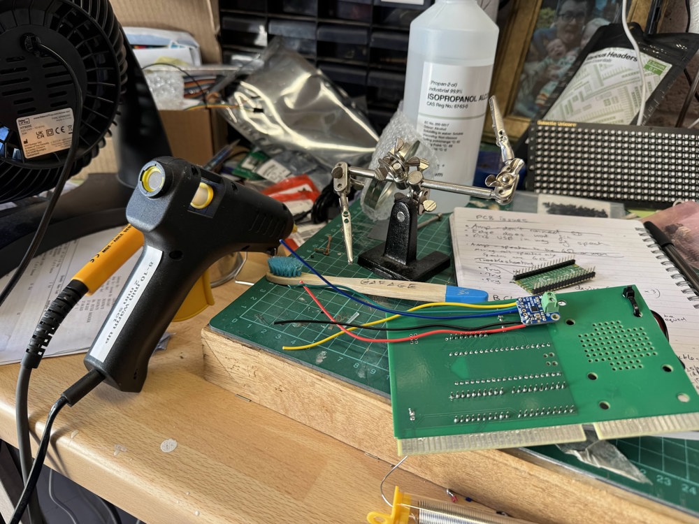
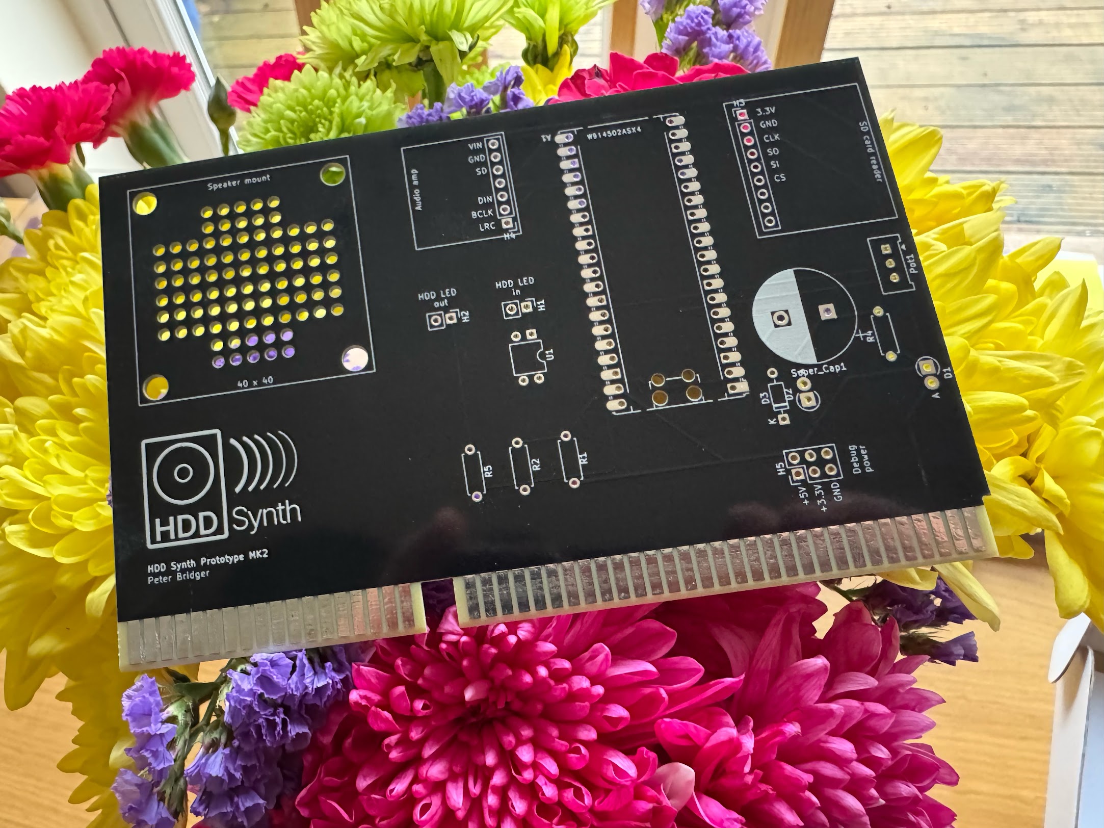
Next steps
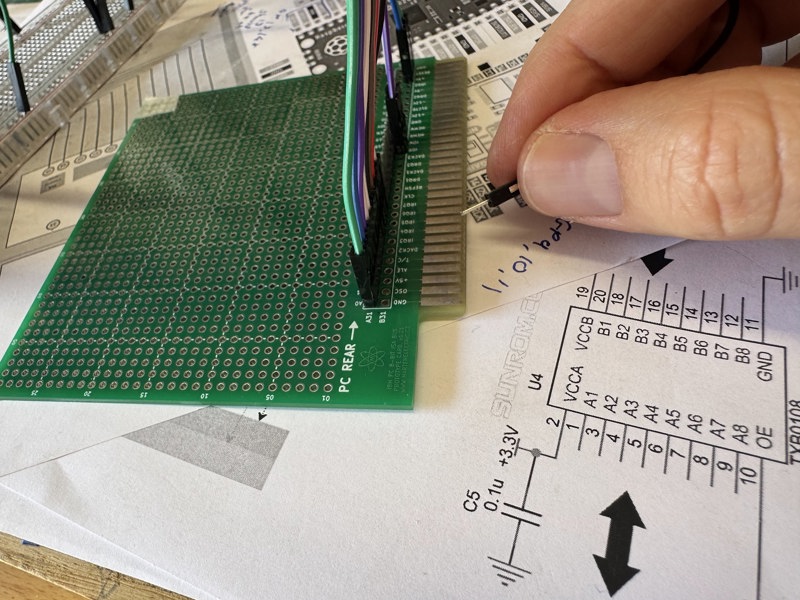
I won't be able to progress this until the weekends (due to work/family life), but the next step is to fit this into an actual PC to prove that it works. Once that's complete I'll make any refinements required then I'll release the full source code and parts list.
If you'd be interested in a prebuilt device let me know so I can determine if it's worthwhile me assembling a set for sale.
Cheers
Peter
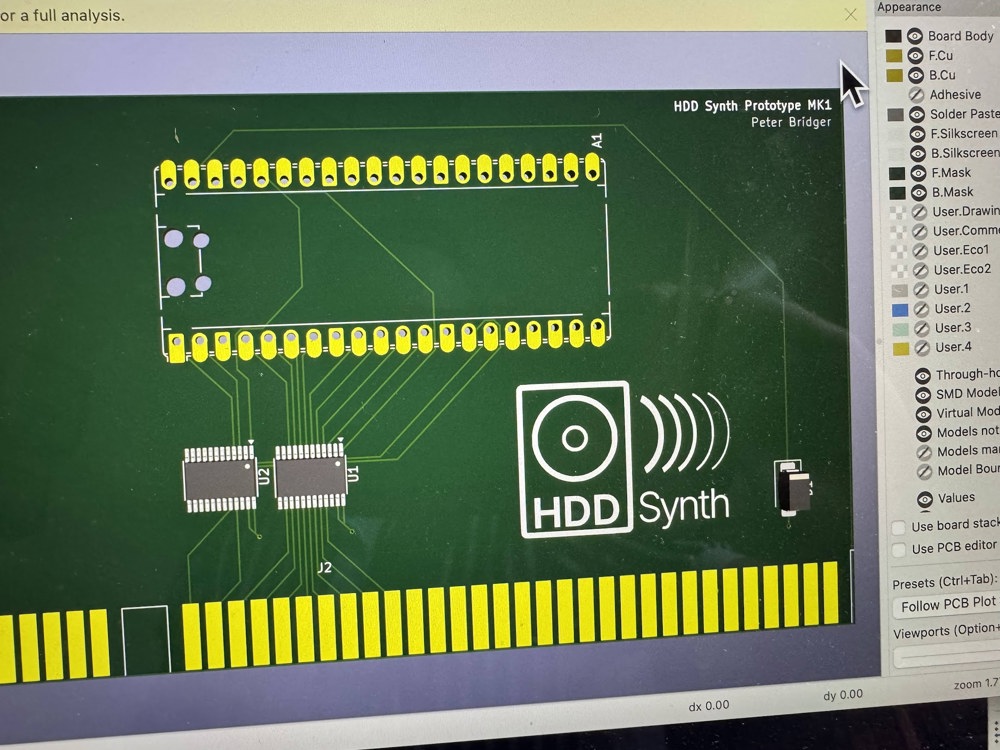
- HDD Synth - Recreates the sound of mechanical spinning HDD
- GameMinder - DOS games launcher