VOGONS


What retro activity did you get up to today?

Topic actions

Reply 30880 of 30901, by wierd_w

User metadata
Rank Oldbie
Rank
Oldbie

I cobbled together an anachronistic retrostation out of an old ASUS laptop today.

https://youtu.be/Rqgvd-eWBOs

I have noticed something "unusual" about the Baron's VSBHDA. If you load the 32bit version of it, then *IMMEDIATELY* unload it and the hdpmi host, load the 16 versions immediately after, unload the 16 bit versions, then reload the 32bit versions *again*, then games that normally only work with the 16 bit version mysteriously start working with the 32bit one.

Getting Wolfenstein 3D working today was kinda the focus of my activities. You can see the automated install/uninstall/install/uninstall/install AGAIN happening in the video, but it's fast.

Reply 30881 of 30901, by TheAbandonwareGuy

User metadata
Rank Oldbie
Rank
Oldbie
Ydee wrote on 2026-02-28, 08:57:
TheAbandonwareGuy wrote on 2026-02-27, 06:07:

Now the question is:

* Will the much smaller Pentium3 heatsink be enough to cooler an Athlon 1500? My guess is its going to be very borderline. I might have to mess around with underclocking/undervolting this thing.
* Will the anemic 100 watt max continous output PSU explode trying to power it?

Bestec ATX100-5 with 10A at 5V rail? And 2A at 12V? If yes, then good luck with Thunderbird or Palomino, integrated GPU and board with 5V only CPU VRM... You will need much better PSU, cable management and some airflow inside the case and even so I am affraid, that heatsink for cca 30W CPU will not be enough for cca 60W. My 5 cents only.

"We do these things not because they are easy, but because they are hard" - John F Kennedy

The PSU is non standard form factor so I cant exactly upgrade it, and the cable management is as good as it's going to get just due to the location of the IDE ports on the board and the confines of the case.

To be clear: No part of this is a good idea. I just wanted to see if I can make it work because if it does it's a fairly neat compact machine. If I end up destroying the hardware, oh well. It's all useless hardware that was destined for the dump anyways.

Cyb3rst0rm.com: Here There Be Screeds https://www.cyb3rst0rm.com
I used to own over 160 graphics card, I've since recovered from graphics card addiction

Reply 30882 of 30901, by Ydee

User metadata
Rank Oldbie
Rank
Oldbie
TheAbandonwareGuy wrote on 2026-03-01, 05:08:

"We do these things not because they are easy, but because they are hard" - John F Kennedy

The PSU is non standard form factor so I cant exactly upgrade it, and the cable management is as good as it's going to get just due to the location of the IDE ports on the board and the confines of the case.

To be clear: No part of this is a good idea. I just wanted to see if I can make it work because if it does it's a fairly neat compact machine. If I end up destroying the hardware, oh well. It's all useless hardware that was destined for the dump anyways.

Indeed, I understand - but: this is custom designed case for set with Celeron CPU (about 20W TDP), some 64-128 MB SDRAM, onboard audio and video, one HDD. For it is 100W PSU maybe ok, consumption could be about 60-70W?). But if you use an Athlon 1400 with about 70W TDP and mobo with 5V CPU VRMs, it simply can not work. You need strong 5V rail on PSU - 25A or more. Now: you need to take the heat away from the processor and heatsink for 20W CPU can hardly cope with three times the radiated heat. And you still need to get him out of a case that doesn't have airflow or vents... Maybe try some low clocked Duron instead, but even so IDK.

Reply 30883 of 30901, by andrea

User metadata
Rank Member
Rank
Member
Ydee wrote on 2026-03-01, 08:52:

Indeed, I understand - but: this is custom designed case for set with Celeron CPU (about 20W TDP), some 64-128 MB SDRAM, onboard audio and video, one HDD. For it is 100W PSU maybe ok, consumption could be about 60-70W?). But if you use an Athlon 1400 with about 70W TDP and mobo with 5V CPU VRMs, it simply can not work. You need strong 5V rail on PSU - 25A or more. Now: you need to take the heat away from the processor and heatsink for 20W CPU can hardly cope with three times the radiated heat. And you still need to get him out of a case that doesn't have airflow or vents... Maybe try some low clocked Duron instead, but even so IDK.

The big issue would be cooling not so much power I think.
I've ran a M810LR with a Thoro-A 2000+, OEM 64bit Rage128Pro and a ALS4000 with the stock 90W PSU out of an HP Vectra VEi8.
I can't remember the rating on the 5V rail, but it was an Astec so probably extremely overbuilt.

A Palomino or a Thunderbird is perhaps a bit much though.
The late Thoro-B Semprons can probabily be undervolted a fair bit and/or mobile-modded* and nobody really wants them so they are still cheap.

*https://fab51.biosbude.de/cpu/barton/athlon-e24.html

Reply 30884 of 30901, by BitWrangler

User metadata
Rank l33t++
Rank
l33t++
onethirdxcubed wrote on 2026-02-28, 23:35:
Ozzuneoj wrote on 2026-02-27, 22:53:

Back plates for cards are still the one thing I can't figure out how to replace. I am not a machinist, I have no tools or shop for working with metal, 3D printed back plates are just not the same... If i could solve the backplate thing I could complete dozens of awesome cards that I've salvaged over the years.

For cards with D-sub connectors that have screw lugs to hold the backplate to the card, all you really need to make your own backplate from a slot blank is a power drill, a set of drill bits, files, clamps, and a block of wood to drill into. I've had to do this for a few cards that met a terrible fate with a scrapper or only came with Low Profile brackets. For cards that don't have any screw lugs for attachment I sometimes steal brackets from WinModems, and rectangular holes can be cut with a Nibbler or a lot of filing.

Yeah, scrap modems are something almost nobody wants and can supply brackets. Key is to have a good stash of them to pick through so the big telephone RJ hole is the center of your biggest connector. Either pick one where at least one bracket hole lines up, or make sure you cut slots just tight enough for the hex screw posts on a D port to hold it on.

However, if you wanna do it from scratch, aluminum, brass and copper are far easier to work with. If you get thinnish plate, you can draw your holes on it, put it down flat on a piece of hard wood, get a nice sharp chisel and pound it round the edges to punch it out. If you have done it in brass or copper, you can tin it afterward to get it silvery so it doesn't look out of place... or polish it for steampunk cred 🤣 .... possibly this can work out with some thin steels also, type you will find in discarded cans that are flat metal... would suggest the base of large "cans" that are cardboard drums... some of those may be aluminum... probably only get one bracket out of the middle though, unless you want some lo-pro too.

Another suggestion, cheap baking sheet... if you get some good metal shears, you can probably cut one of those, preserving the edge for the top right angle bracket... saves problems of bending it straight... find one with a good sharp corner though, not an overly rounded one. Probably thicker steel than you find in discarded cans, but not so thick you can't use shears on it.

Unicorn herding operations are proceeding, but all the totes of hens teeth and barrels of rocking horse poop give them plenty of hiding spots.

Reply 30885 of 30901, by HanJammer

User metadata
Rank Oldbie
Rank
Oldbie

I recapped the neckboard of my NEC Multisync 3D monitor basically fixing the problem which was crippling it since I got it few years ago (same problem as described here: https://www.leadedsolder.com/2024/03/19/nec-j … crt-repair.html )!

It required adjustment. Tube is very bright and sharp and colors are great! Can't wait to test it on something else than regular VGA (like all 80s NEC Multisync monitors it supports both analog and digital RGB / CGA, EGA, Amiga, Atari ST, Macs, Apple IIGS and odd japanese hardware...

And yesterday I replaced power switches in my Philips CM8833 and Commodore 1084S-P1.

New items (October/November 2022) -> My Items for Sale
I8v8PGb.jpg

Reply 30886 of 30901, by Shponglefan

User metadata
Rank l33t
Rank
l33t

Continued to work on my electronics repair work bench in a never ending quest for a more optimal setup.

The attachment Workshop March 2026.jpg is no longer available

I recently added an articulating arm for my microscope to the stand off the desk. This let me re-arrange my soldering setup and reclaim some space.

I also recently upgraded my soldering station to a Hakko FX-972 and added a stand for my desoldering gun.

The attachment Workshop - Soldering Setup March 2026.jpg is no longer available

And last, added some proper fume extraction replacing the tabletop smoke absorber I'd be using previously. This one uses a flexible plastic arm which I can move out of the way when not needed.

The attachment Workbench Fume Extraction.jpg is no longer available

Pentium 4 Multi-OS Build
486 DX4-100 with 6 sound cards
486 DX-33 with 5 sound cards

Reply 30887 of 30901, by Ozzuneoj

User metadata
Rank l33t
Rank
l33t
Shponglefan wrote on Yesterday, 02:29:
Continued to work on my electronics repair work bench in a never ending quest for a more optimal setup. […]
Show full quote

Continued to work on my electronics repair work bench in a never ending quest for a more optimal setup.

The attachment Workshop March 2026.jpg is no longer available

I recently added an articulating arm for my microscope to the stand off the desk. This let me re-arrange my soldering setup and reclaim some space.

I also recently upgraded my soldering station to a Hakko FX-972 and added a stand for my desoldering gun.

The attachment Workshop - Soldering Setup March 2026.jpg is no longer available

And last, added some proper fume extraction replacing the tabletop smoke absorber I'd be using previously. This one uses a flexible plastic arm which I can move out of the way when not needed.

The attachment Workbench Fume Extraction.jpg is no longer available

Looks like an awesome setup. One thing though, for me personally, I would cover the back of those CRTs with something if they have to stay there. When I'm doing a lot of soldering work there are times when I find a little hard piece of solder or a stray leg clipped from a capacitor on the floor under my desk. If you were sitting at the desk and some conductive bit managed to go from your desk to your lap and then into the back of a CRT, bad things could happen. 😀

Now for some blitting from the back buffer.

Reply 30888 of 30901, by gerry

User metadata
Rank l33t
Rank
l33t
Shponglefan wrote on Yesterday, 02:29:

Continued to work on my electronics repair work bench in a never ending quest for a more optimal setup.

what a great set up, well organised but also tidy! (for now 😀 ) You certainly have a good set of tools there, lots of things you can do

Reply 30889 of 30901, by appiah4

User metadata
Rank l33t++
Rank
l33t++

Started repair work on two new 486 motherboards, both battery damaged. One looks like a lost cause, so I started on the other. There are some exploded tantalums (which I will replace with low ESR electrolytics, fuck tantalums) and some broken ceramics I don't know the value of. The other ceramics on the board are 10pf-22pf-27pf-47pf and 10nf which is a huge jump. Tryint to figure out what that capacitor value is some way..

Reply 30890 of 30901, by Shponglefan

User metadata
Rank l33t
Rank
l33t
Ozzuneoj wrote on Yesterday, 04:36:

Looks like an awesome setup. One thing though, for me personally, I would cover the back of those CRTs with something if they have to stay there. When I'm doing a lot of soldering work there are times when I find a little hard piece of solder or a stray leg clipped from a capacitor on the floor under my desk. If you were sitting at the desk and some conductive bit managed to go from your desk to your lap and then into the back of a CRT, bad things could happen. 😀

That's a good point! Certainly any stray metal falling into the CRTs would be bad news. Fortunately I've mostly done work standing and only recently added a stool to use at this bench. So I don't think anything has fallen into the monitors previously, but I'll definitely double check before I power any of these up.

I do need to work out some better CRT storage though. The shelf they are sitting on is sagging a lot since it wasn't intended to whole their weight. I am currently working on building some additional shelves, so I may relocate them soon.

gerry wrote on Yesterday, 08:57:

what a great set up, well organised but also tidy! (for now 😀 ) You certainly have a good set of tools there, lots of things you can do

Thank you! It took a long time to evolve into its current state, but I'm quite happy with it now. 😁

Pentium 4 Multi-OS Build
486 DX4-100 with 6 sound cards
486 DX-33 with 5 sound cards

Reply 30891 of 30901, by Shponglefan

User metadata
Rank l33t
Rank
l33t

Had the Roland SC-55 MkII on the bench again.

I had to decided to try cleaning more of the switches, with the intent of possibly cleaning all of them.

However, after cleaning two more switches I decided against it. While the disassembly and cleaning is fine, the reassembly is a pain. Trying to get the metal top to sit flush on the switch is difficult at best. And I noticed that after reassembly, the actuators were more loose than when originally assembled.

This doesn't seem to impact performance of the switch itself, but given the time it takes to clean them this way, it's not worth it.

I spec'd out some replacements on Digikey and ordered up a 100 of them, along with some 2200uF caps. Once I get those I can fully replace these switches and cap and finally be done with this unit.

Pentium 4 Multi-OS Build
486 DX4-100 with 6 sound cards
486 DX-33 with 5 sound cards

Reply 30892 of 30901, by Nexxen

User metadata
Rank l33t
Rank
l33t
appiah4 wrote on Yesterday, 12:46:

Started repair work on two new 486 motherboards, both battery damaged. One looks like a lost cause, so I started on the other. There are some exploded tantalums (which I will replace with low ESR electrolytics, fuck tantalums) and some broken ceramics I don't know the value of. The other ceramics on the board are 10pf-22pf-27pf-47pf and 10nf which is a huge jump. Tryint to figure out what that capacitor value is some way..

Starting a thread?

PC#1 Pentium 233 MMX - 98SE
PC#2 PIII-1Ghz - 98SE/W2K

- "One hates the specialty unobtainium parts, the other laughs in greed listing them under a ridiculous price" - kotel studios
- Bare metal ist krieg.

Reply 30893 of 30901, by Shponglefan

User metadata
Rank l33t
Rank
l33t

Worked on one more sound module this evening, a Roland SC-88.

The attachment Roland SC-88 powered on.jpg is no longer available

It had the usual glue around several capacitors.

The attachment Roland SC-88 capacitor glue.jpg is no longer available

I removed the capacitors and cleaned up the glue. All three caps tested fine so I resoldered them back on.

While inspecting solder joints on the rear ports, I noticed that the joints for the audio in/out looked like they had been previously reflowed. Not only that, but the ground pin for the left output seemed like it had a broken solder joint. It was moving as I flexed the port.

There was a lot of nasty flux in the existing solder, so I decided to wick it away for cleaning. In the process I discovered that the loose joint was actually a detached pad. The entire pad came away with the solder.

The attachment Roland SC-88 missing pad.jpg is no longer available

To fix it, I fashioned a makeshift pad out of a piece of diode leg. I bent into a circlet shape before squishing it down with pliers. After exposing some copper trace next to the missing pad, I then soldered it in place. Flexing the rear connector no longer causes any movement on the repaired solder joint.

The attachment Roland SC-88 repaired pad.jpg is no longer available

Pentium 4 Multi-OS Build
486 DX4-100 with 6 sound cards
486 DX-33 with 5 sound cards

Reply 30894 of 30901, by lepidotós

User metadata
Rank Member
Rank
Member

Spending some time with a GeForce 2 MX in one of my Power Macs and I've been severely underestimating the 2 MX this entire time, it seems. RTCW at 35-ish fps 1024x768 or 65-ish at 640x480 (at 85 hz on a CRT, maxed settings) is way smoother and nicer looking for those framerates than I'd ever expected, for some reason I was expecting something closer to the Nintendo 64. And that's in Tiger, I have yet to run the game in Jaguar or 9.

"I have to blow everything up! It's the only way to prove I'm not crazy!"
—Dr. Gordon Freeman, May 2000

Reply 30895 of 30901, by Ozzuneoj

User metadata
Rank l33t
Rank
l33t

Is "Suddenly realizing that something you threw away many years ago was actually really cool" a retro activity?

Because I just did that.

I was reading something here on the forums about dual processor systems and it suddenly popped into my head that when I built a new computer for a friend's business back in ~2008, he gave me his old computer. It had been built for him many years prior and had been a fairly expensive custom built thing... most likely because he told the shop he needed something fast to run some mapping software and no self respecting computer shop in the late 90s would miss an opportunity to maximize profits on a "special" system built for a business. :rofl

Anyway, I have always remembered that this system was equipped with dual Socket 370 Celeron Mendocino processors, but it JUST hit me like five minutes ago that this is actually really unusual, and I have not come across any boards like that in the 10+ years I have been buying old hardware.

I googled it and found this wikipedia article about the Abit BP6 and, sure enough, this was a really unique setup and the Celeron was never intended for SMP. I don't know if that's the board he had or if it was something different, but... man. I think I still have the processors, but I had basically no room to keep anything at that point in my life so I definitely didn't keep that computer around for long. I have no idea where it ended up exactly.

Add that board to the list of neat stuff that I should have held onto...

Now for some blitting from the back buffer.

Reply 30896 of 30901, by ChrisK

User metadata
Rank Member
Rank
Member
ChrisK wrote on 2026-02-27, 15:43:
Will do asap. Give me a moment. […]
Show full quote
Shponglefan wrote on 2026-02-26, 17:21:
ChrisK wrote on 2026-02-26, 16:56:

Still had this board around so I thought why not give it a shot with my new self-made(TM) preheating station (which for itself was a long planned project but only got realized within the last weeks):

Can you share more about how you set this up?

I've long considered getting a board heater and also trying to rig something up for BGA chip rework. I'm really curious what your set up is like.

Nexxen wrote on 2026-02-26, 17:29:

Like above, some more info? 😀

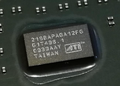
Btw, what diameter are the pads and the solder balls you are going to use?

Will do asap.
Give me a moment.

Sorry for the delayed reply. Had to take some days off over the weekend.

Regarding the preheater, that's a project I was after for quite some time now.
I didn't want to spend that premium share for some professional stuff nor did I opt to buy one of those cheapo ones from aliexpress that come already bent and twisted.
So why not build one on your own? How hard can that be?

In the end there's not so much to tell about: the case is from an old STB, bottom heaters are two 400W ceramic heating plates controlled by one of those REX-C100 PID-controllers from China and its bundled SSR (own story, needless to say: don't trust what's printed on them, however, for this project it doesn't matter).
The PID-controller does a half-way good job. Sometimes it overshoots with temperature but this may be partly due to chosen PID values, where I still have to fine tune, and it also depends on the size of the PCB that gets heated. If the PCB is big then there's not much ventilation under it compared to a smaller PCB giving the system another time constant which influences the regulation. At least I think that this is what changes the overall behavior depending on what you work on. But all in all it's very much usable. Really amazing how effortless you get thermal energy pumped into even a full motherboard heating it to 130°C and more.

For the top heater I used a smaller variant with 200W which only got an on-off switch for now. I had plans to implement a reflow controller with display, network, reflow profiles support (just dreamin', haha). But for now manual control seems to do fine. Temperature is controlled with a separate multimeter.

Most other parts I had laying around or bought for cheap: some aluminium profiles from a 3D printer, metal plates from an optical drive case (sorry LG), some wires, power socket, fuse holders, electrical isolation material, rods from an old lamp holder, 3D printed parts to fit all together, a lot of screws and probably some more stuff like that. The most it takes is creativity to bring it all together and KNOWING WHAT YOU DO since this uses MAINS VOLTAGE. Sufficient electrical isolation is essential as well as knowing what parts get hot and could influence that isolation.
Speaking of that, the top heater still needs some refinement regarding electrical isolation. The current build state was more like "let's first see if it can do at all". It can.

It'd also be wise not to use something round for the beam. With a round shape you'll have to counter any torque acting on it such as with my hot air gun holder (mounted on the leading end in the pic). It works for now but if it bothers me too much I might change that.

Well, that's all to say about it I guess.

RetroPC: K6-III+/400ATZ @6x83@1.7V / CT-5SIM / 2x 64M SDR / 40G HDD / RIVA TNT / V2 SLI / CT4520
ModernPC: Phenom II 910e @ 3GHz / ALiveDual-eSATA2 / 4x 2GB DDR-II / 512G SSD / 750G HDD / RX470

Reply 30897 of 30901, by tehsiggi

User metadata
Rank Member
Rank
Member
ChrisK wrote on Today, 11:25:

Well, that's all to say about it I guess.

I love it. That hits a nerve for me! In the good way!

--

Modded a Radeon 9600 Pro today to have temperature sensing via software.
Radeon 9600 Pro temperature sensing mod

The attachment 96pro_temp.JPG is no longer available

AGP Card Real Power Consumption
AGP Power monitor - diagnostic hardware tool
Graphics card repair collection

Reply 30898 of 30901, by appiah4

User metadata
Rank l33t++
Rank
l33t++
Nexxen wrote on Yesterday, 23:56:
appiah4 wrote on Yesterday, 12:46:

Started repair work on two new 486 motherboards, both battery damaged. One looks like a lost cause, so I started on the other. There are some exploded tantalums (which I will replace with low ESR electrolytics, fuck tantalums) and some broken ceramics I don't know the value of. The other ceramics on the board are 10pf-22pf-27pf-47pf and 10nf which is a huge jump. Tryint to figure out what that capacitor value is some way..

Starting a thread?

Yes.

Reply 30899 of 30901, by ChrisK

User metadata
Rank Member
Rank
Member
tehsiggi wrote on Today, 11:31:
ChrisK wrote on Today, 11:25:

Well, that's all to say about it I guess.

I love it. That hits a nerve for me! In the good way!

😀

RetroPC: K6-III+/400ATZ @6x83@1.7V / CT-5SIM / 2x 64M SDR / 40G HDD / RIVA TNT / V2 SLI / CT4520
ModernPC: Phenom II 910e @ 3GHz / ALiveDual-eSATA2 / 4x 2GB DDR-II / 512G SSD / 750G HDD / RX470