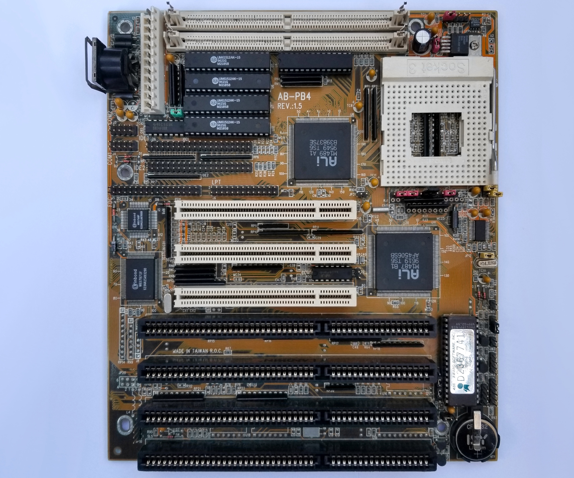
Almost an year ago posted here about AbitAB-PB4 revision 1.3 486 class motherboard.
Great hardware for up to 160MHz, but couple of things bothered me with it:
- the on-board clock generator supports 60/66MHz frequencies required for 180/200MHz to CPU but there is no jumper configuration to enable them. Manual talks about JP31 but it is not present in PCB revision 1.3, so FSB cannot be higher than 40MHz.
- completely unstable system with P24T (POD83/100)
I happen to have revision 1.5 of the same motherboard but it was stuck at 5V to CPU which prevented me from running most 4x86/5x86 processors on it.
Been on my to-do list to fix that and examine it properly.

Most notes from the original post hold true for this one too, with the next differences:
The non-standard slot from revision 1.3 is replaced with normal 16-bit ISA slot.
JP31 is there.
JP12 is not soldered in position 1-2.
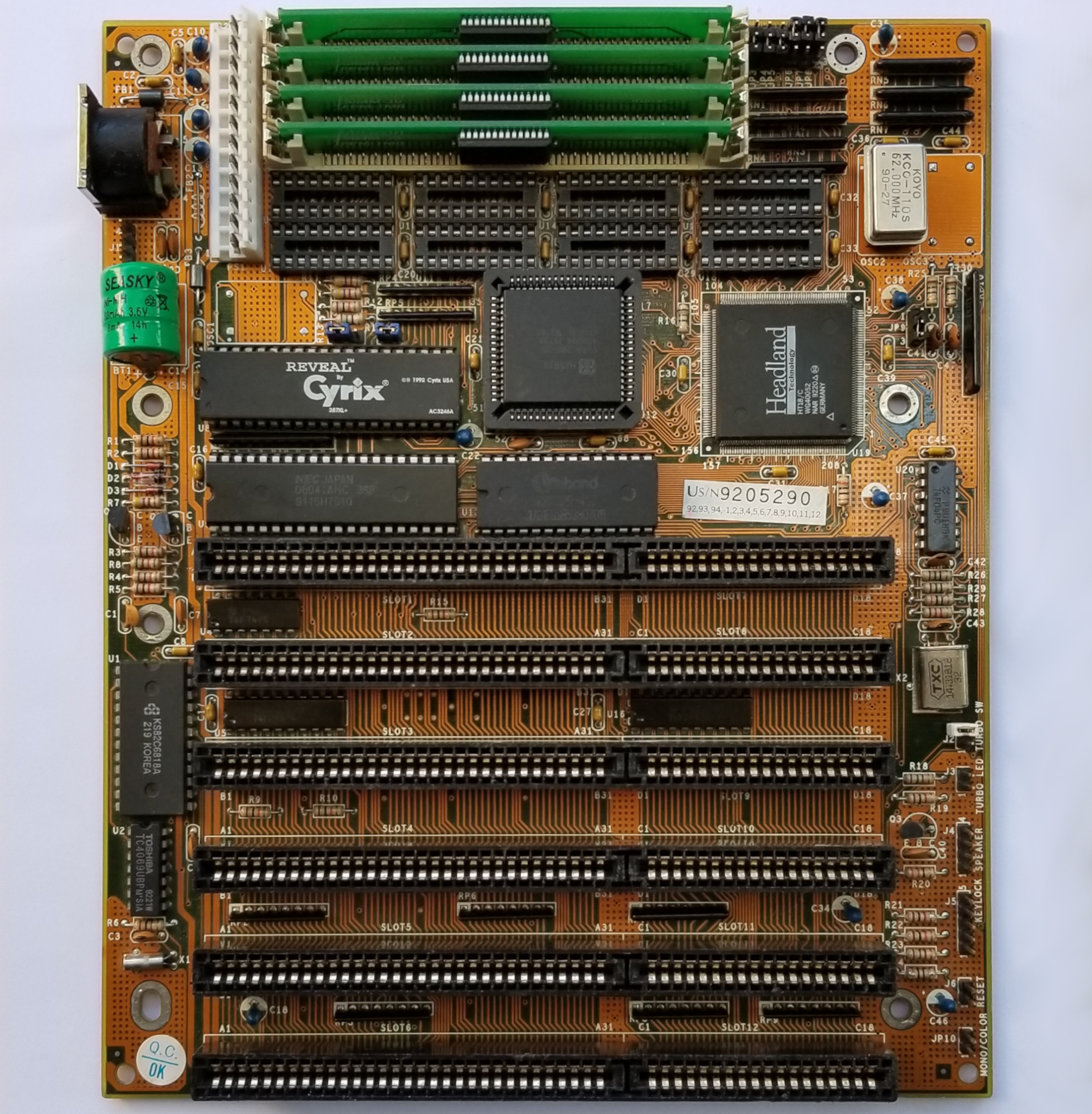
Comparing the voltage regulators of the two boards (upper-right corner) gives a hint about the possible problem.
revision 1.3:
The attachment left_side.jpg is no longer available
revision 1.5:
The attachment right_side.jpg is no longer available
Swapped the VRMs - instant success with 1.5.
1.3 got stuck at 5V. Will have to upgrade it to the same 5 legged linear VRM at some point later.
Clear sign of design flaw in both PCBs.
--- Am5x86 @ 160MHz
With proper VRM everything worked as expected with 4x86 and 5x86 CPUs.
With all BIOS settings on max the system gets quite picky about RAM modules and L2 cache chips.
Took me a moment to find the right combination.
Ended up with 256Kb L2 cache and 64Mb 60ns EDO RAM.
No point to go past 64Mb since it will be out of the cacheable range.
SpeedSys looks the same as the screenshot from the provided above link to the first post.
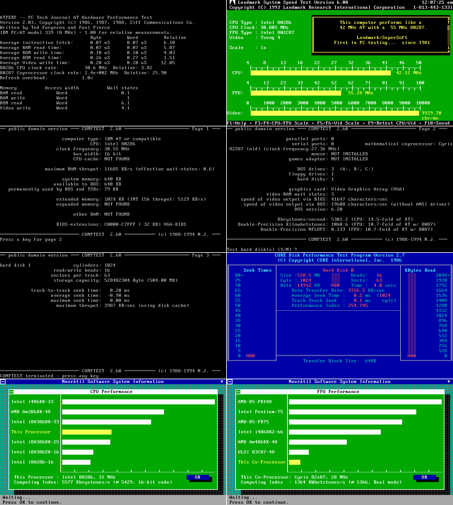
benchmark results
It is clear that Abit made optimizations to revision 1.5 as it is consistently faster than 1.3 with WinTune2 (accelerated Windows GUI) being the only exception. That difference is more of a rounding error than anything else.
The improvements get performance closer to the best numbers on record. Pretty nice.
IDE interface without driver hits around 5Mb/s reported by SpeedSys and CoreTest.
With driver the local storage i/o hits 9-10Mb/s which is on par with Asus PVI (best on-board IDE, etc.)
--- Am5x86 @ 180MHz
No combination of jumpers seems to produce 60MHz FSB. Will check this more carefully in the coming days, but so far no lights beyond 50MHz FSB.
--- Am5x86 @200MHz
3x66MHz is not possible. No jumper settings seem to produce 66MHz FSB.
System is fully stable at 4x50MHz, 200MHz CPU.
All BIOS settings on max except:
DRAM READ TIMING = FAST (best is FASTEST)
SRAM READ TIMING = 3-1-1-1 (best is 2-1-1-1)
4V to CPU for complete stability.
SpeedSys reports really nice IDE metrics.
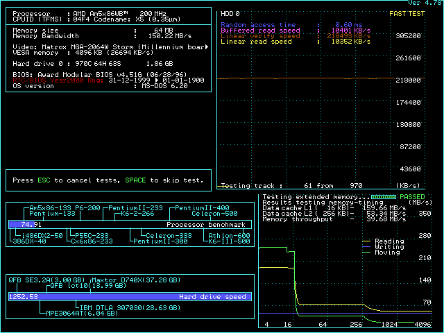
benchmark results
Obviously not the best performer out there, but ticks pretty well for what it is.
Feels really solid - completely trouble free - very satisfying.
--- P24T (POD83/100)
PODs work much better on revision 1.5 than 1.3 but still very flaky.
No amount of tweaking produced stable system - different voltages, most conservative BIOS settings, etc.
Really disappointing.


