At any rate, you should measure the current draw on the wire that you are powering the peltier to ensure that you aren't overloading the cable. If you are close to the rated capacity, you might want to rethink how the peltier is connected, or use a less powerful peltier.
I have re-confirmed that the v12.41 detonator driver works with GLQuake on an Am5x86. At 160 MHz, I get around 27.5 fps. UUD board.
Yes. Cannot remember the readings anymore, but range felt comfortable.
Tried briefly last night with MX400 on LSD - still no OGL, also some other instabilities.
Inconclusive what is going on. Will need more attention.
Thanks for the confirmation.
At max.
Yes, i know - it makes sense that way.
Convenient for casual daily use.
Not great for tech/sci stuff.
I am confused about what voltage you are running your TEC1-12715 at. I recall you saying that you use them at 12 V rather than 5 V because, empirically, they appear to work better. But in your statement on page 30, you are quoting the 5V molex connector for the peltier, implying you are now running the TEC at 5 V. Which is it?
In looking at the spec sheets for US-produced TEC1 devices, there are charts for input voltage, current, heat pumped, and deltaT. From the chart, the maximum current draw occurs at the top end of the input voltage range, or 15 V, not 12 V. The current draw looks fairly flat over the range of deltaT (0 C to 70 C).
I connected a TEC1-12715 to a variable DC supply and connected an current meter in line. I placed different heatsinks on the hot and cold sides of the peltier pads.
For TEC1-12715 (China sourced, no brand), this is what I measured.
3.3 V = 0.92 A
5.0 V = 1.40 A
12 V = 2.6 A
15 V = 4.16 A
15 V should measure 15 A for the TEC1-12715. So either the specs are wrong, I am interpreting the specs wrong, or there is a much larger dependency on current draw for deltaT variations than the US graphs show. I am using the US graphs because the Chinese manufacturers didn't supply them.
Plan your life wisely, you'll be dead before you know it.
Initial setup was with smaller heatsinks, 12V to fan and 12V to Peltier.
Later on switched to bigger fan/heatsink and 5V to fan and peltier.
Yes, i looked-up some of these charts. At 5V the Peltier is significantly weaker, both at current draw and thermal transfer.
As i mentioned early - the datasheets shared on ebay by sellers are messy and confusing. So at some point i dropped it - it was confusing me.
That's why i mentioned early that anchored to specific voltage to the Peltier and played with the cooling setup. The factors involved, one more time for clarity:
- Voltage to Peltier, kept it constant because of confusion over specs
- Heatsink size, shape, material
- fan airflow
- amount of thermal paste applied - not enough of it and the whole thing turns into a toaster
It is hard to keep track of what your latest running conditions are. But if my test numbers are correct, running the 12715 run at 5 V is probably similar to a 12702 at 12 V, which is the unit I now have on order.
Without the vasoline, do you still get water vapour condensing onto the ceramic surface? And what about on the actual 486 pins? I assume you cannot put vasoline on the pins due to lack of electrical conductivity.
Plan your life wisely, you'll be dead before you know it.
Sorry about that. I already edited the original post like 10+ times - filling some gaps when i remember about them.
Still need to add a picture of the final cooling setup and tweak some of the wording so it makes sense.
Hard to tell what the difference will be between 12702 and 12715 - hope you can provide the details at some point soon.
If i remove the silicon that fills the gap between upper side CPU, side of peltier and bottom of heatsink, then water condensation will eventually occur.
Initially i contributed this to the temperature difference between CPU surface and ambient/air, but it is actually coming from the close proximity of hot/warm upper side Peltier + bottom heatsink and the cooler top/side CPU.
No condensation on the bottom of the CPU.
Still, i am going to keep both the silicon on the sides and the vaseline on the bottom of the CPU.
I should probably add these notes to the original post too. Well doing it now.
Applied Feipoa's 1024Kb L2 cache mod to one of the Biostar MB-8433UUD-A version 2 motherboards.
It is straightforward to do, does not take much time, so it made sense to give it a try.
That was the easy part.
Finding the right L2 cache chips was a nasty experience, especially if tightest BIOS timings are a requirement.
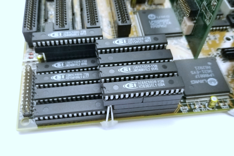
At the end a combination of ISSI 10/15ns rated chips did the job. Well, at 160MHz at least.
Here is how the final assembly looks like.
Tripple-decker to give space for the chips in bank 0 to be handled easily.
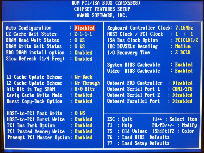
--- 160MHz
1024Kb L2 cache running with the tightest BIOS timings:
System is very stable. Passed everything i threw at it (and i don't hold back).
Very satisfying.
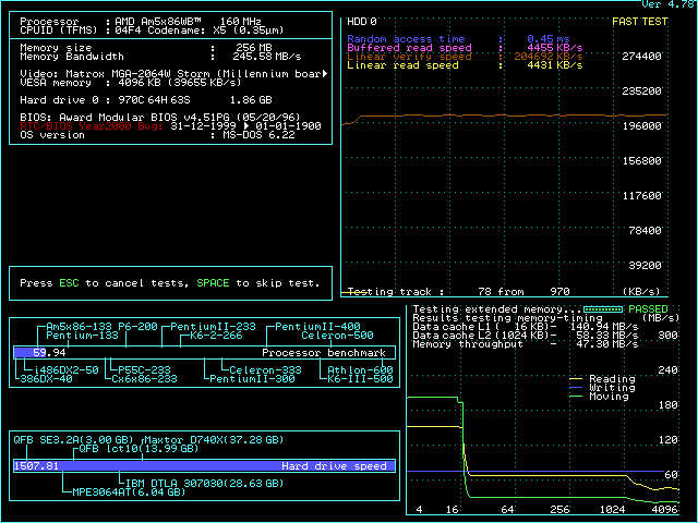
Here is what SpeedSys says.
Notice the 256Mb (50ns EDO) RAM.
The UMC IDE driver was difficult as usual. Refuses to cooperate when BIOS settings are on max.
Have to lower its disk speed argument value to 9-10 otherwise it hangs. At that point performance is lower than no driver.
Additional L2 cache improves performance. Chart below shows this mobo's best scores with 256Kb and 1024Kb L2 cache, as well as the best scores from everything else i have seen so far - for reference.
Notice the Quake 1 result - finally a system that outdoes in some way Asus VLI at its game - 8-bit pixel pushing.
In addition to improved performance, the increased L2 cache size allows for fully covered 256Mb address space.
So maxing out the system memory makes this configuration even better.
Basically, fully maxed out UUD experience.
EDIT: Noticed that with some adz/adw processors 4v vcore may be recuired.
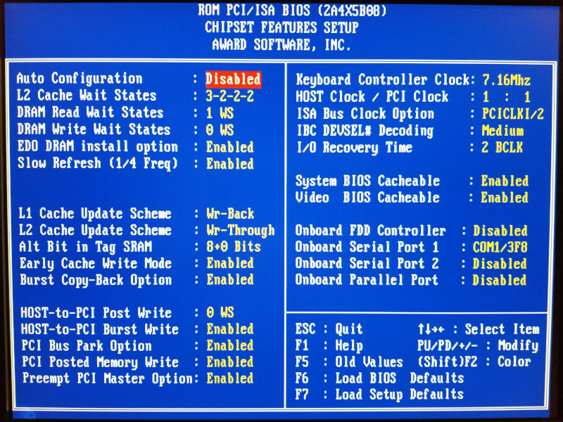
--- 180MHz
Things didn't work that well at this frequency.
There seems to be a limitation on the motherboard side. It refuses to boot if L2 CACHE WAIT STATES is not 3-2-2-2 (slowest) and DRAM WAIT STATES lower than 1.
What makes me think it is the mobo ?
Usually when trying to find the right combination of L2 chips there are sets that result in at least partially stable system - some apps/games/tests work, others don't.
This is a good indication that the limitations are on the cache chips side.
In this case anything faster than 3-2-2-2/1 results in hard hang during post, regardless of what cache chips are being used at the moment.
Tried hard to overcome that, but the board refuses to cooperate. Even at 3-2-2-2/1 the system is not fully stable - things are ok with interactive DOS graphics, but Windows and the more challenging tests are unpredictable.
Also, over 64Mb of system RAM further worsens stability.
Disappointing.
While the extra L2 cache offsets to a point the inflated BIOS timings, it is still not enough to outdo 256Kb at full speed.
If at least the system was fully stable, the extra cache could be a nice option for fully covered 256Mb of system memory.
I was hoping for a better outcome at 180MHz, but that didn't happen.
Had the intention to use the Biostar UUD board as a base for that fast 486 PC from few posts ago. Wanted an UMC chipset in the mix, but LuckyStar D scales better beyond the 160MHz, which is hard to ignore.
Last edited by pshipkov on 2021-11-24, 21:25. Edited 1 time in total.
How long did it take you to find the right combination of SRAM modules to work at 1024K, 160 MHz, and 2-1-1-1 timings? And does that particular order of modules matter? I assume it does. Unfortunately, I don't have a lot of different brands of 128kx8 modules to try out like you. I have dozens of the Chinese fakes and only 4 pieces of original 128kx8 modules from the 90's.
This is interesting, since you went triple decker, you don't have to lift up the DIP sockets that overhang the left-most bank? Doesn't the pin header get in the way though? I normally remove all SRAM modules from the right-most side of the dips on this motherboard because of the header.
I also noted that the DOS UMC 8886BF driver doesn't like a 40 MHz PCI bus. Did the UMC Windows driver fare any better? Nonetheless, the issue with the UMC 8886BF can be overcome with an add-on card.
Did you extensively test 256 MB FPM memory at 40 MHz?
I also noticed that with 66 MHz, I must limit the system to 3-2-2-2 and DRAM read at 1WS. It looks like 60 MHz is no exception. But what about 50 MHz and 1024K? However, unlike you, the IBM 5x86c-133/2x is perfectly stable in Windows, at least mine is. What CPU voltage are you running? When I was doing tests with 66Mhz, 3-2-2-2/1ws, and 128 MB, I found that increasing the CPU voltage helped, which is curious, because I didn't have to do this with 64 MB.
I am confused by the two benchmark charts. In the first chart, UUD/1024K shows 18.9 fps in Quake1, while the second chart shows UUD/1024K at 20.0 fps. Could you clarify?
If it is any consultation, I suspect the LSD board modded to accept 1024K would suffer the same fate at 60 MHz.
With any luck, the HxC or FloppyFlash firmware will fix your issue with the LSD and the Gotek.
Plan your life wisely, you'll be dead before you know it.
How long did it take you to find the right combination of SRAM modules to work at 1024K, 160 MHz, and 2-1-1-1 timings? And does that particular order of modules matter? I assume it does. Unfortunately, I don't have a lot of different brands of 128kx8 modules to try out like you. I have dozens of the Chinese fakes and only 4 pieces of original 128kx8 modules from the 90's.
This last time it took few hours, but was doing other things as well.
Order matters. Swapping chip in slot 0 with chip in slot 1 can be the difference between fully stable and flaky.
I don't have that many 128kx8 chips. Once i got into the retro optimize and overclock thing, i had to scrub some of the motherboards i have here from their chips.
The 10ns "fake" ones are good in my opinion.
This is interesting, since you went triple decker, you don't have to lift up the DIP sockets that overhang the left-most bank? Doesn't the pin header get in the way though? I normally remove all SRAM modules from the right-most side of the dips on this motherboard because of the header.
The space is just enough to allow chips to be inserted easily without lifting the sockets. In a moment of wisdom the simple idea came to me.
Was thanking myself multiple times during the hours of chips curation. 😉
I also noted that the DOS UMC 8886BF driver doesn't like a 40 MHz PCI bus. Did the UMC Windows driver fare any better? Nonetheless, the issue with the UMC 8886BF can be overcome with an add-on card.
Yes, the DOS driver gets unstable at 40MHz or more with tight timings.
The Windows driver worked.
ATTO, speedsys and coretest do not agree on numbers.
Timing a copy of big file shows that UMC Win drivers are slightly slower than the Win95 native ones.
Yes, Promise, SiS, Adaptec, etc., PCI Ultra-ATA controller takes care of the on-board IDE nonsense.
Was thinking to strap one to that 180MHz PC.
I also noticed that with 66 MHz, I must limit the system to 3-2-2-2 and DRAM read at 1WS. It looks like 60 MHz is no exception. But what about 50 MHz and 1024K? However, unlike you, the IBM 5x86c-133/2x is perfectly stable in Windows, at least mine is. What CPU voltage are you running? When I was doing tests with 66Mhz, 3-2-2-2/1ws, and 128 MB, I found that increasing the CPU voltage helped, which is curious, because I didn't have to do this with 64 MB.
Hmm, good question. Didn't test 1024Kb L2 cache @50MHz.
It will be interesting what happens there.
Checked both stock 3.45V and 4V. Same result.
But i know what you mean very well. In some of the other motherboards i pushed recently at 60/66MHz FSB i noticed that increasing CPU voltage can sometimes enable the system to work at tighter L2 cache and memory timings. An interesting phenomenon.
Mentioned this in one of the previous posts.
Good to know that you are stuck at 3-2-2-2 when running at 66 MHz. Well, it is not good really, but you know what i mean.
Can you get below 3-2-2-2 at all, even very unstable ?
I am confused by the two benchmark charts. In the first chart, UUD/1024K shows 18.9 fps in Quake1, while the second chart shows UUD/1024K at 20.0 fps. Could you clarify?
That is correct. May need to further emphasize it in the previous post, so it is more clear.
256Kb @ 2-1-1-1 is faster than 1024Kb @ 3-2-2-2.
It might be helpful for you to get a socket 3 interposer module and setup a trimmer on it so that you can have variable 3 to 4 V adjustment on any system.
I am not even able to get an unstable system at 66 Mhz and faster than 3-2-2-2 for the L2.
Why is there the 18.9 fps vs. 20.0 fps difference in Quake1 scores with UUD/1024K? What setting was changed?
Do you intend to try 512K double-banked on the UUD board?
No, I haven't tried those other firmwares. I started a thread asking for advice, but didn't get any useful replies. Gotek floppy emulator and Linux?
Plan your life wisely, you'll be dead before you know it.
Was thinking about that.
The other day i discovered 2 of these modules in a bag with parts from a DIY 3D printer that somebody gave me.
So far didn't need it because the CPUs seems to be crunching well in the motherboards i am interested in at 3.45-4V without side effects.
I will be mainly interested if can drop voltage below 3.45.
Thanks for the 3-2-2-2 clarification.
Framerate difference: The first table is for 160MHz the second one is for 180MHz.
Or i don't understand your question.
Yes, i will try 512k in two banks. See what happens ...
I saw the thread but didn't have anything meaningful to add compared to our prior conversation.
I guess trying it is the only way.
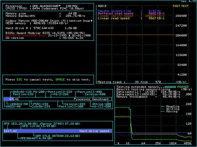
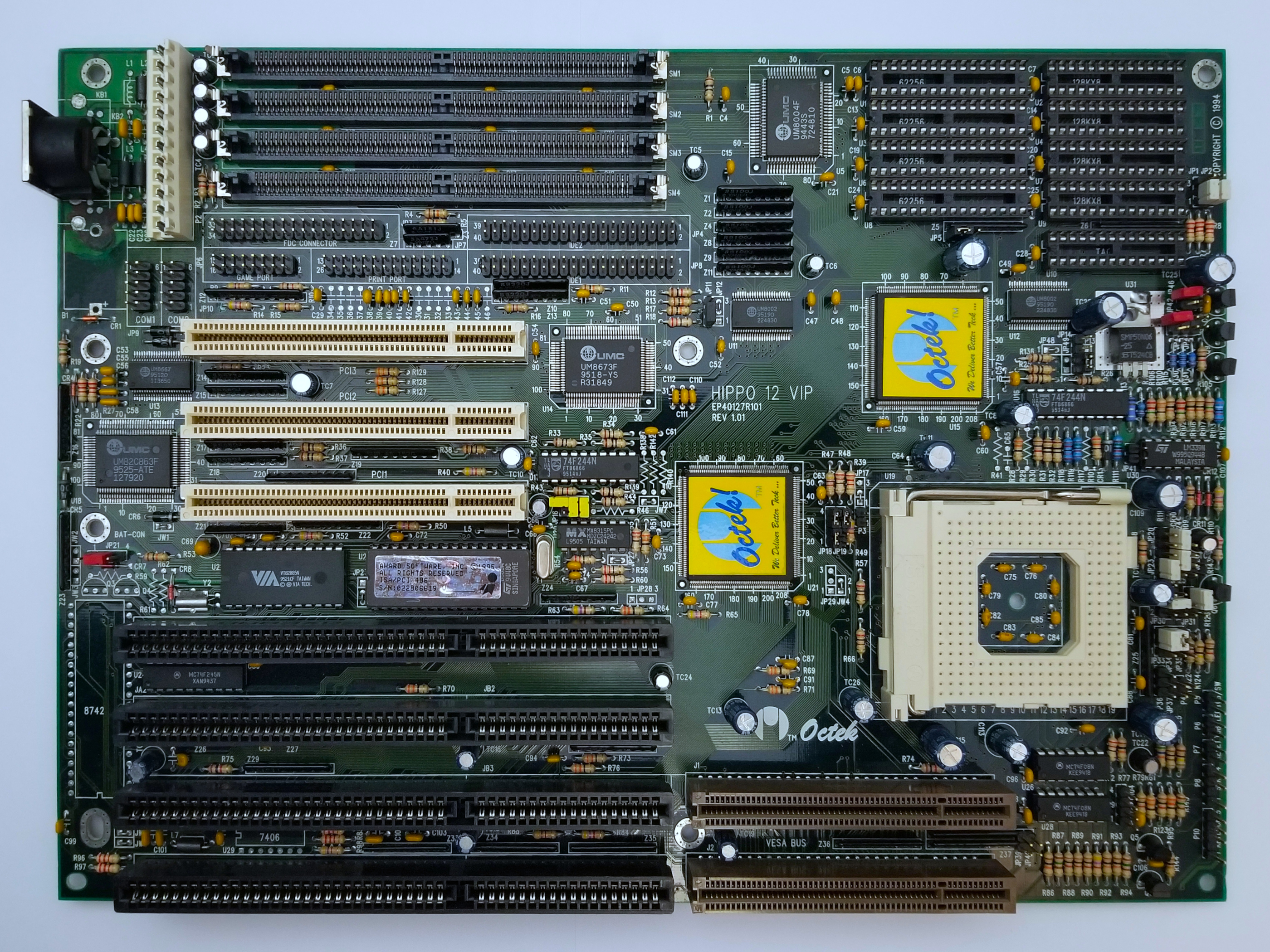
I am kind of through with the 486 at 180MHz - an exercise in practicality epic, but recently examined Octek Hippo 12 VIP revision 1.01, so decided to post the info - for completeness.
The use of large amount of through-hole components confirms the early birth of this motherboard, which is also printed in the upper right corner - year 1994.
Where "early" is in the context of PCI + UM888 chipset adoption.
Distinguished candy shop look - "very cool" yellow-blue stickers and multi-colored components.
Saw it on ebay for $350 - ridiculous, but since i have a soft spot for VIP boards - proposed $90, seller bumped back up, pushed back down, settled on $140 - still a lot but in a moment of weakness went for it.
Came crisp in a new antistatic back. No dust, no, nothing. New electronics smell.
There was a scratch on the back near the second VLB slot which cut through 2 lines. Fixed it a minute later.
Easy on the L2 chips - takes pretty much any of them. Liked that.
Performance-wise 256Kb L2 in two banks > single bank 512Kb.
Also, performance is better with L2 cache policy set to Write-Back.
This is unusual, since all other boards based on the UM888 chipset do better with L2 cache in WT mode.
Didn't use third party VLB or PCI IDE controllers, instead wanted to see what the onboard UMC one can do.
UMC IDE drivers don't behave well with tightest BIOS timings - the usual.
Tested with:
Matrox Millennium PCI and S3 Trio64 VLB graphics cards. Ark1000VL didn't work on this board, so used the S3 Trio64 instead.
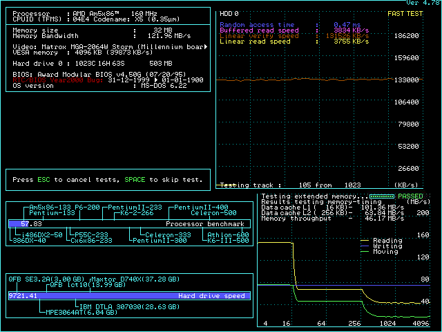
There is no support for EDO RAM in the BIOS, so used single 32Mb of 60ns FPM module. 128Mb work well too, but over 32Mb + L2 in WB mode = lowered performance.
Good board, very easy to setup and run. Obviously not a the best performer out there.
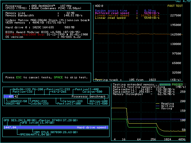
--- 180MHz
3.45V to CPU or no boot.
DRAM WAIT STATES = 1
VLB video cards don't light-up at 60MHz base frequency.
Initially i had a lot of stability issues at 180MHz - couldn't complete POST.
At some point i disconnected by accident one of the Peltier wires during POST and suddenly the system was in DOS prompt.
Light bulb flashed. Until then i used 300W PSU. Swapped with 450W - all good from there on.
This is the first motherboard that exhibits such a problem, but is indication that using Peltier elements with underpowered PSUs can be too close to the electric stability threshold of some hardware configurations.
Speedsys:
Benchmarks, compared to Biostar UUD and LuckyStar D as the highest watermark.
At this frequency the motherboard does just fine in DOS, but is unstable in Windows and some of the more complex tests.
Tried hard to overcome that. Long story short - limitation is in the board itself.
Performance scales well - considering how much behind the 160MHz results were it closes the gap at 180MHz.
Still, the shown instabilities make it unsuitable for OC past 160.
--- 200MHz
No lights.
Last edited by pshipkov on 2023-02-20, 03:16. Edited 2 times in total.
pshipkovwrote on 2021-09-24, 07:49:Applied Feipoa's 1024Kb L2 cache mod to one of the Biostar MB-8433UUD-A version 2 motherboards.
It is straightforward to do, doe […] Show full quote
Applied Feipoa's 1024Kb L2 cache mod to one of the Biostar MB-8433UUD-A version 2 motherboards.
It is straightforward to do, does not take much time, so it made sense to give it a try.
That was the easy part.
Finding the right L2 cache chips was a nasty experience, especially if tightest BIOS timings are a requirement.
At the end a combination of ISSI 10/15ns rated chips did the job. Well, at 160MHz at least.
Here is how the final assembly looks like.
Tripple-decker to give space for the chips in bank 0 to be handled easily.
Hi pshipkov, if you find some time could you share how to perform this version of the mod?
@feipoa is still around to answer related questions. You can always ping him.
The explanation is in a document he published here: http://vogonsdrivers.com/getfile.php?fileid=946&menustate=0
Very easy to do, but you need to stare at the description for a moment.
Modified second LuckyStar E486 rev D motherboard.
This time with 8ns L2 cache chips. Thinking to attempt long-term sustainable 200Mhz system.
To my surprise the silk screen reacted badly to the heat gun:
The attachment 20211017_192627.jpg is no longer available
Took the picture straight out of the oven. After cleaning and removing the residual material from the pins and the slime from the surface things look much better, but that upper area and two spots below burned more than i would like.
The previous board that underwent the same procedure came out crisp. Not sure why this PCB took more damage.
Any tried and good ideas how to re-silk screen it ?