VOGONS


3 (+3 more) retro battle stations

Topic actions

Reply 1621 of 2154, by CoffeeOne

User metadata
Rank Oldbie
Rank
Oldbie
pshipkov wrote on 2023-01-03, 15:59:

Revision 2.0 of of the Asus VLI motherboard does not have these jumpers. Only 2.1.

My posting should show the jumpers for Rev. 2.1., Revision 2.0 is missing the jumper which allows to set 3.3 volts and 4 volts.
Is your board not looking like that? So you have a third jumper or something?

Reply 1622 of 2154, by pshipkov

User metadata
Rank Oldbie
Rank
Oldbie

I misled you with my previous message.
There is no 5V option with the jumpers.

May be good to check if POD CPUs take 5V directly from power rail connected to the corresponding pins.
As far as i remember PODs work all the time in VLI boards regardless of what the CPU voltage jumpers are set to.

retro bits and bytes

Reply 1623 of 2154, by CoffeeOne

User metadata
Rank Oldbie
Rank
Oldbie
pshipkov wrote on 2023-01-05, 16:38:
I misled you with my previous message. There is no 5V option with the jumpers. […]
Show full quote

I misled you with my previous message.
There is no 5V option with the jumpers.

May be good to check if POD CPUs take 5V directly from power rail connected to the corresponding pins.
As far as i remember PODs work all the time in VLI boards regardless of what the CPU voltage jumpers are set to.

I think so too. The POD wants 5 volts.
We would need to do something with the VOLDET pin:

for AM5x86:
"
Most Socket 3 motherboards have jumpers, allowing you to set the voltage manually. Some boards don't have jumpers, but have voltage autodetect instead. These systems check the VOLDET pin (pin S4) on the microprocessor when the system is powered on.

The VOLDET pin is tied to ground (Vss) internally to the microprocessor. If you cannot find any jumpers for setting voltage, you can check the motherboard as follows: Switch the PC off, remove the microprocessor, connect pin S4 to a Vss pin on the ZIF socket, power on, and check any Vcc pin with a voltmeter. This should read 3.45 (± 0.15) volts. See the previous section on CPU sockets for the pinout.
"
So I think when S4 is not connected (from the CPU to the board, best done with an in-between-socket?)
Vcc should be 5 volts.

Reply 1625 of 2154, by TheMobRules

User metadata
Rank Oldbie
Rank
Oldbie
CoffeeOne wrote on 2023-01-05, 18:35:

So I think when S4 is not connected (from the CPU to the board, best done with an in-between-socket?)
Vcc should be 5 volts.

There is a jumper on VL/I motherboard that connects the VOLDET pin to the input of a 7407 whose output is in turn connected to a mosfet gate. This does the switching between using the regulator output or the 5V line as the VCC of the CPU depending on whether VOLDET is grounded or not. Leaving this jumper off gives you a fixed 5V VCC regardless of VOLDET. No need to use interposers or anything.

In rev. 1.8 and below, this is done on pins 4-5 of JP20. Not sure about the 2.x versions, but it should be simple enough to probe with a multimeter in the jumper area until you find a pin that connects to VOLDET in the CPU socket. One of the pins next to it should connect to one of the inputs of the 7407 chip nearby, those should be the pins that you want to leave disconnected if you want fixed 5V.

Reply 1626 of 2154, by pshipkov

User metadata
Rank Oldbie
Rank
Oldbie

The last of the planned 1Mb level 2 cache 486 motherboards.

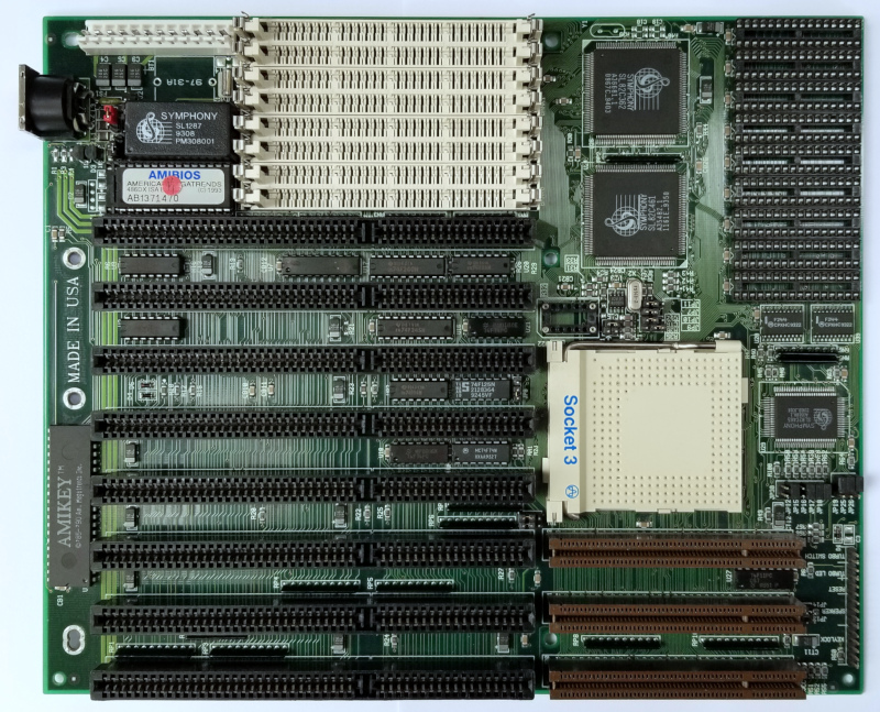
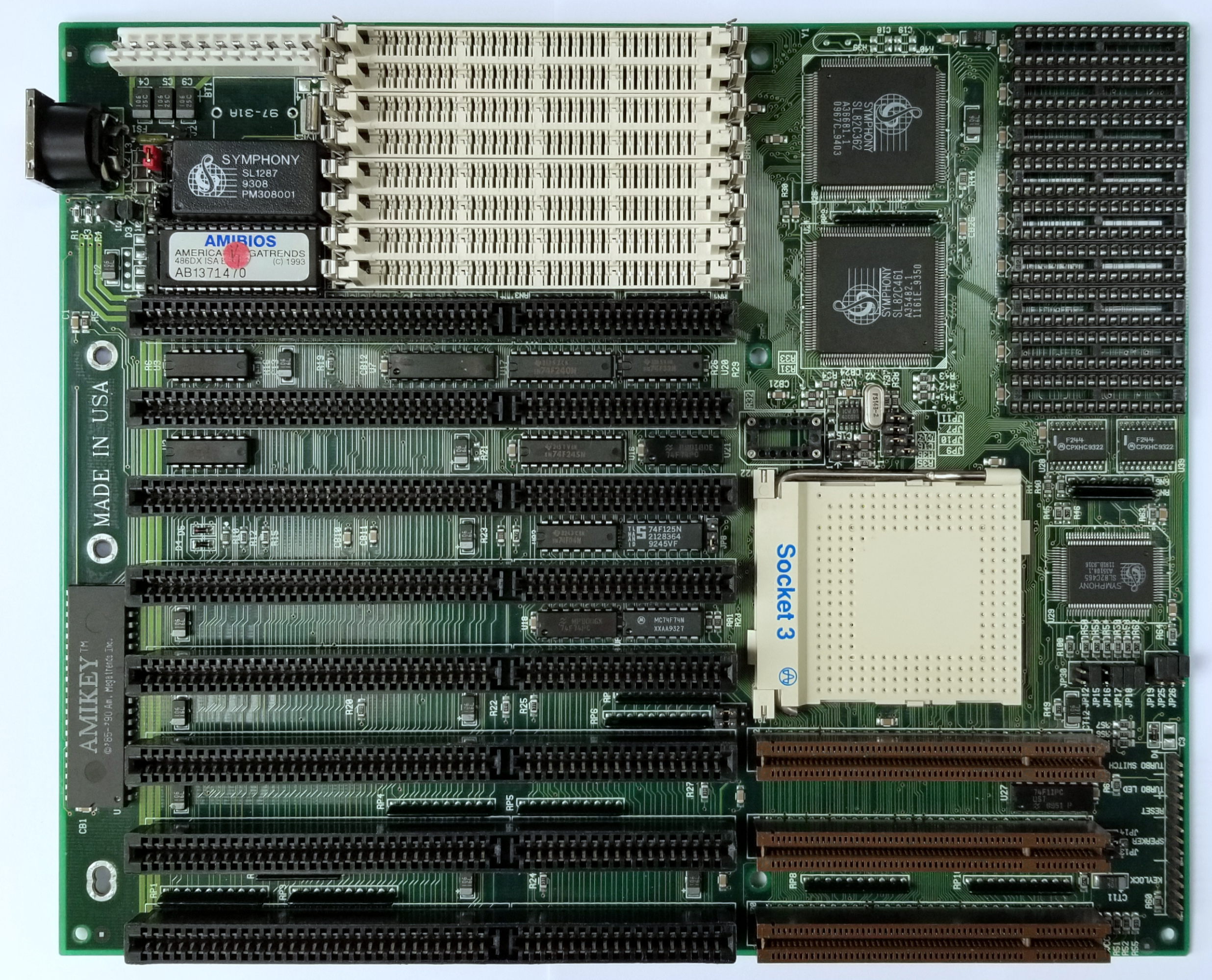
Young Micro Systems VEGA MB-SYP243LV-V12 based on Symphony Labs Haydn II chipset (SL82C632, SL82C461, SL82C465).

motherboard_486_yms_vega_mb-syp243lv-v12.jpg

There was great level of interest around this motherboard for several reasons:
- Haydn II (SL82C460) is the fastest chipset for 386 class processors. By far.
- It is also the fastest chipset for early 486 ISA motherboards - better than anything SiS, UMC, VIA, OPTi were able to put at the time.
- But the next variant - Wagner 82C490 was nothing to brag about, especially when it comes down to VLB support. Offerings from SiS (such as 471) and UMC were much better.
So i wondered if the 460 variant coupled with VLB support will be a silver bullet for 486 VLB systems ?

Looking up the motherboard's manual was not inspirational.
Support only 25/33/50 MHz base frequencies (with the craziest jumper setup i have seen so far to switch between them).
No voltage regulator on board, so 5V only to CPU.
No mention of later 486 CPUs and Overdrives.
30-pin SIMM memory modules only.

Also, few more motherboards from Young Micro Systems passed through here already and none of them were good.

There are crystal oscillators sockets next to the clock generator which made me wonder if i can augment the frequencies through them. Small chance, but worth the try.
Turned-out unsuccessful. Oscillators in the range of 14.xxx to 30 MHz are handled in the same way producing the predefined 25/33/50 MHz frequencies. Input signal above 30MHz results in no lights.
That is with the 2-pin passive oscillator.
There is a 4-pin full can socket as well but oscillators plugged into it appear to do nothing.
Didn't spend much more time to figure it out since the outcome from the 2-pin oscillators already proved unsuccessful at tampering the base frequencies.

BIOS is very basic. 2 parameters only for tweaking performance- ISA bus clock divider and DRAM wait states.
Both set to their optimum values.
Tried with microcodes from DTK PEM-4036Y BIOS - no observable difference in behavior.
Wagner 82C490 BIOSes don't work with this board.

L1 cache for Am5x86 processors is set to WT by default. No jumper to control that. Used interposer to adjust it. Performance improves with that.
Not picky at all about level 2 cache chips. Which is great.
Perhaps the biggest bummer - no VLB EISA controllers work with the motherboard/chipset. Fell-back on ISA IDE.

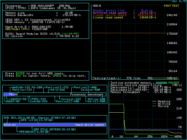
--- Am5x86 @150MHz (3x50)

Since there is no option for 40MHz FSB going for 150.

All BIOS settings on max.
Stuff just works - very stable and satisfying, but for some reason Speedsys hangs.
That's pretty much it.
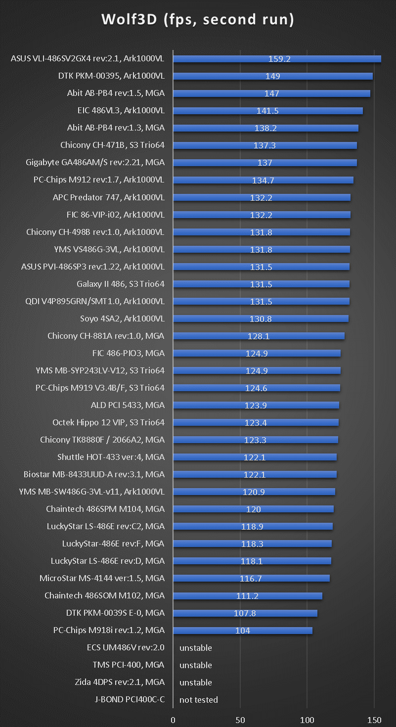
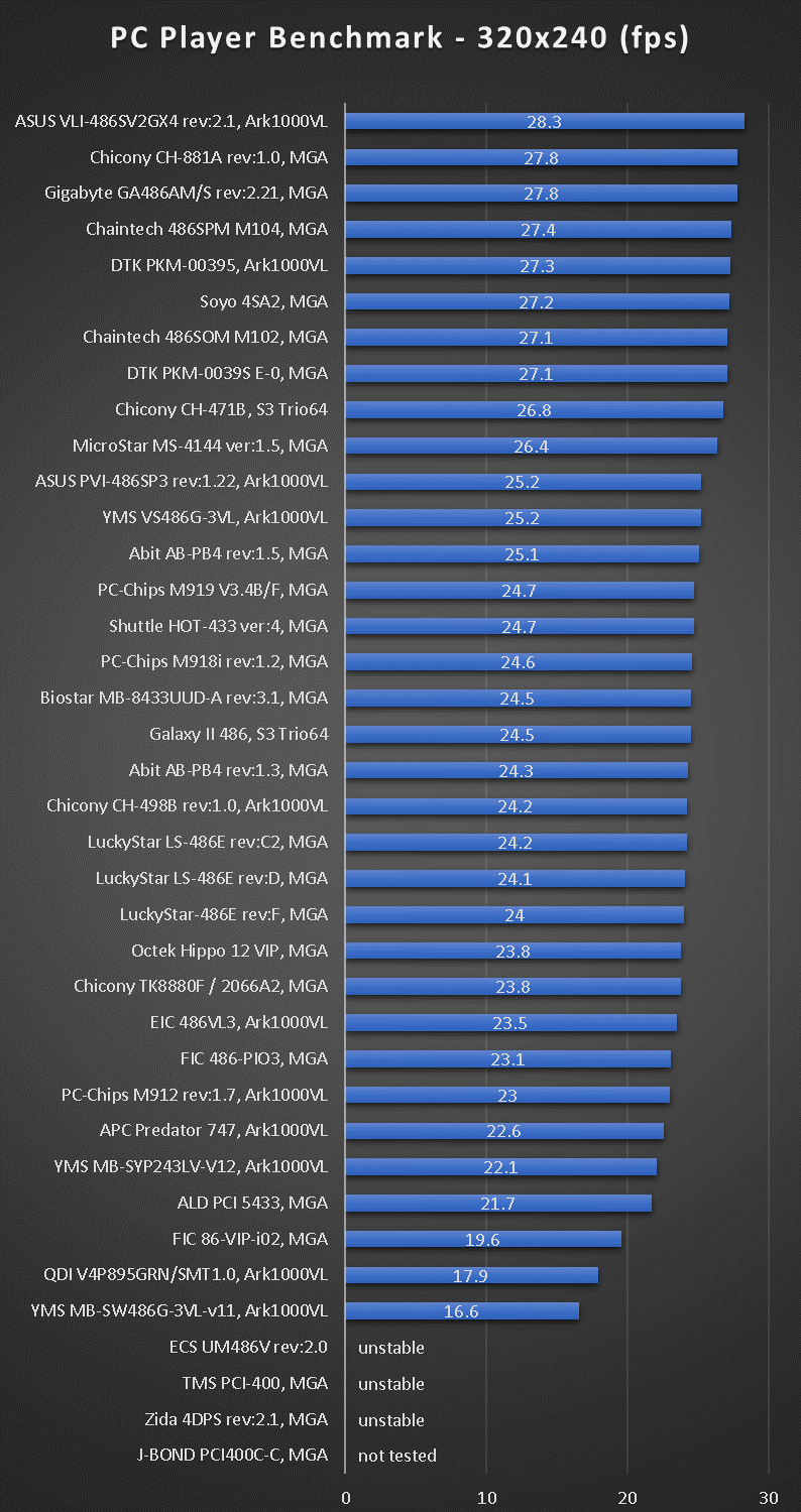
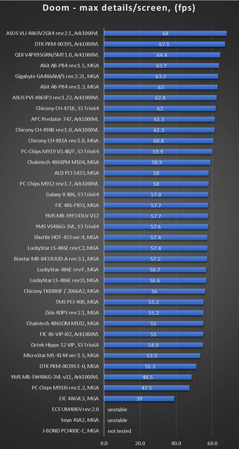
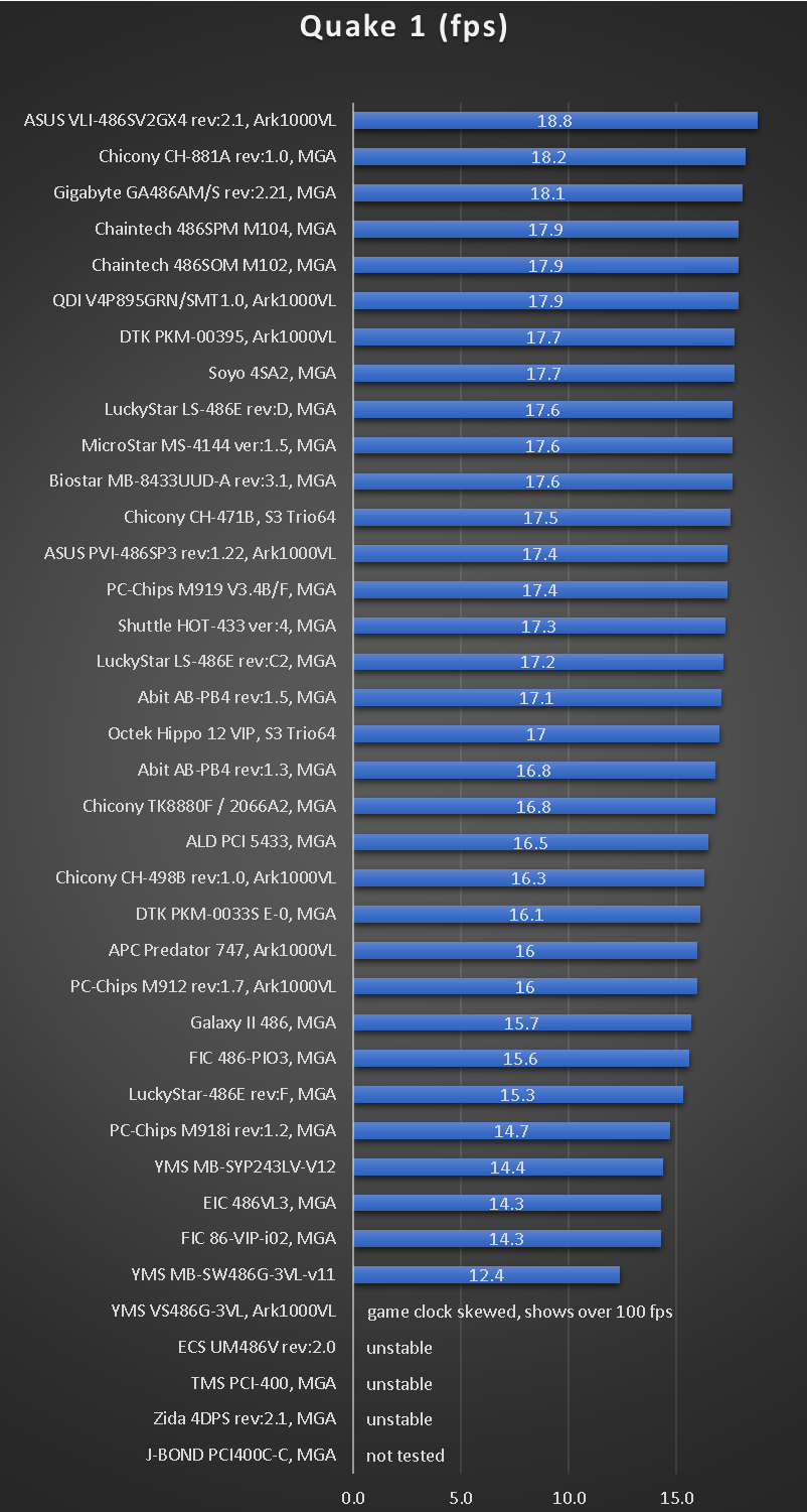
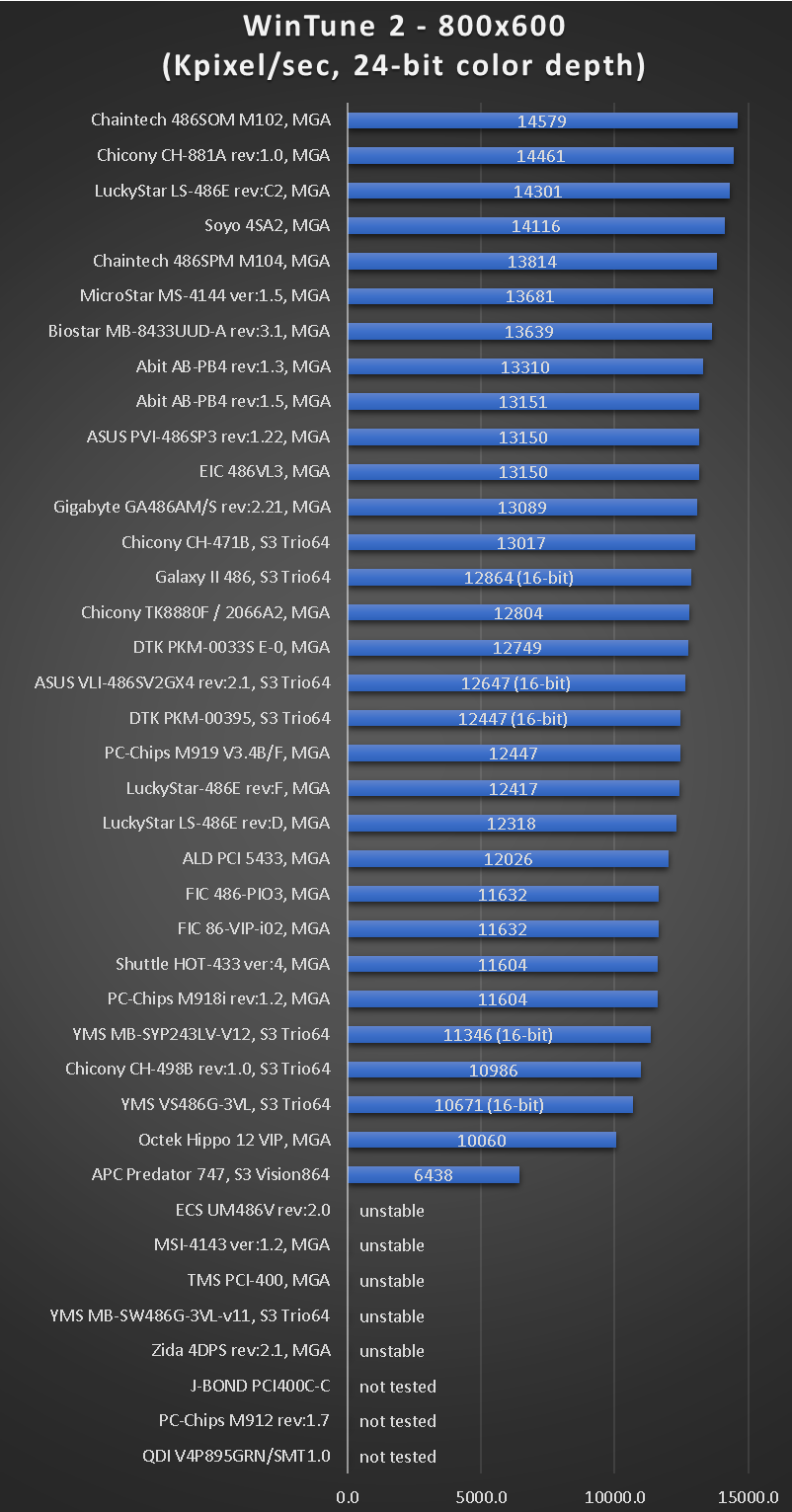
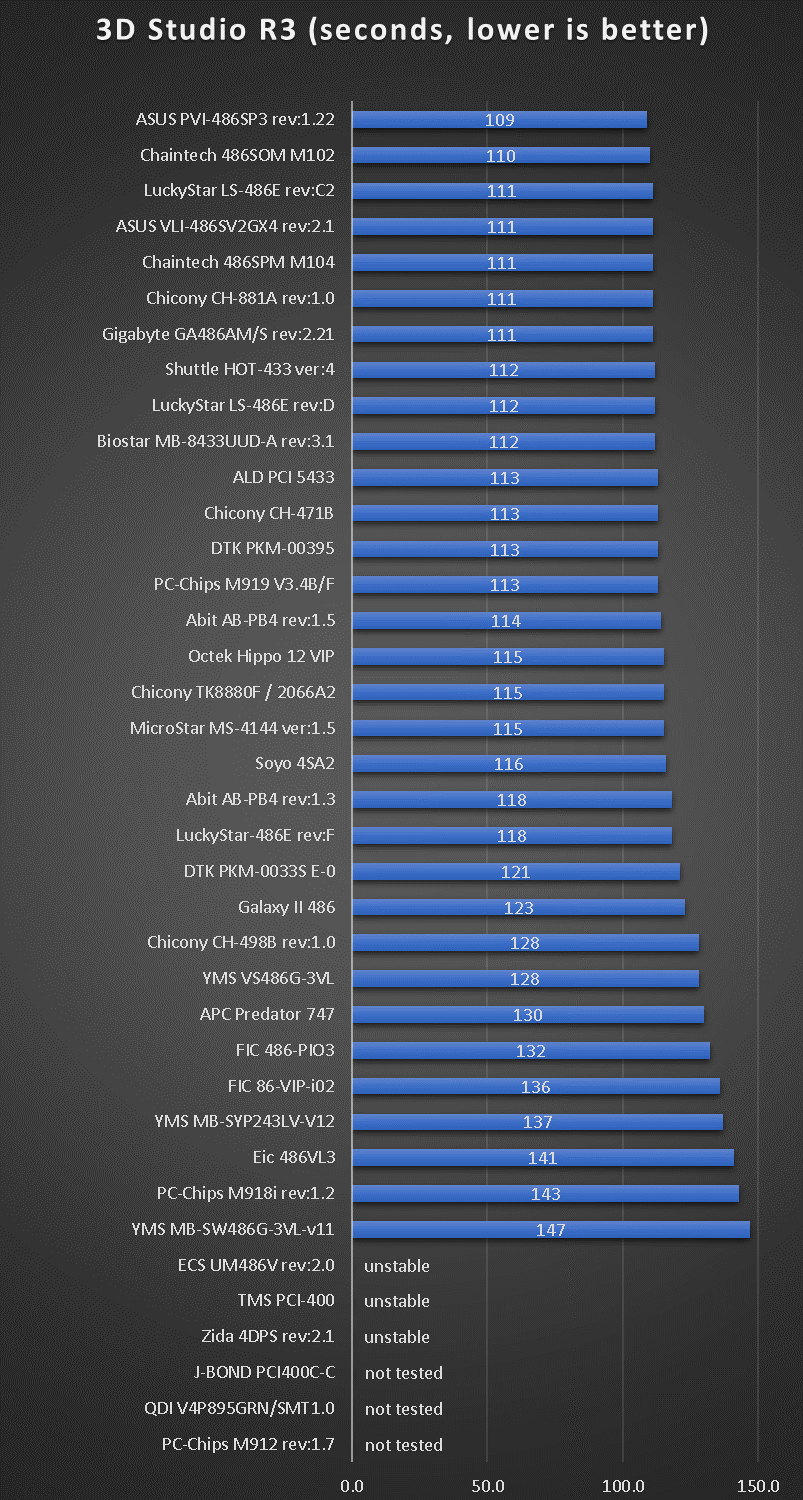
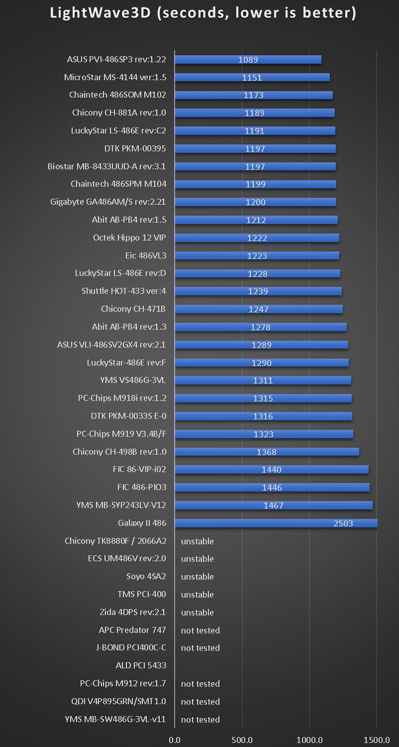
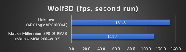
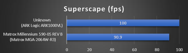
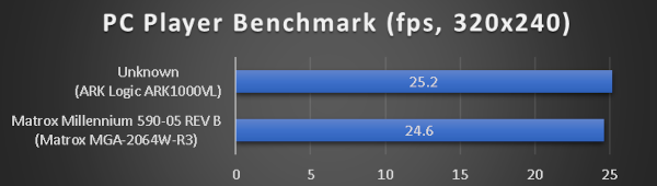
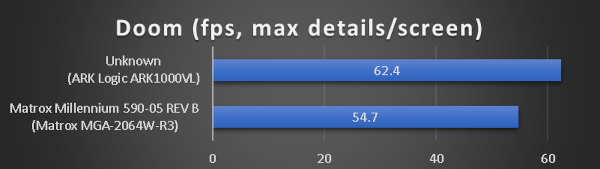
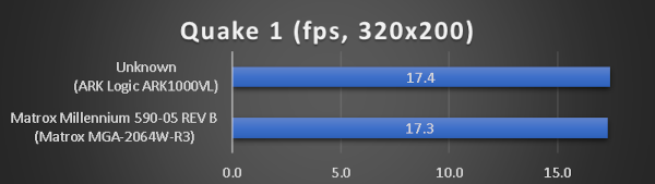
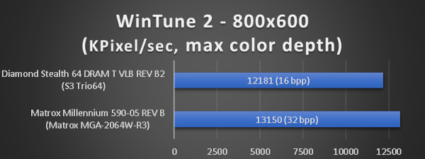
benchmark results

Does not look very good. Mid to low performer.

--- Am5x86 @200MHz (4x50)

Had to increase the ISA BUS CLOCK SELECTION otherwise the system gets unstable.

SpeedSys works just fine in this configuration.
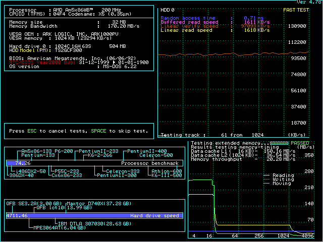
yms_vega_mb-syp243lv-v12_speedsys_200.png

benchmark results

Slow and not fully stable system.

--- Intel Pentium Overdrive P24T

Things work with POD83 but this configuration is of little interest to me.
The lack of 40MHz FSB option prohibits POD100, so didn't spend more time on the Penmtium Overdrive.

---

Clearly one of the first VLB assemblies by Young Micro Systems. Too many loose ends.
Feels like the Haydn II chipset was a limiting factor in several ways.
Wanted it to be a silver bullet, but that's not the case.

Last edited by pshipkov on 2024-03-23, 18:14. Edited 2 times in total.

retro bits and bytes

Reply 1627 of 2154, by pshipkov

User metadata
Rank Oldbie
Rank
Oldbie
TheMobRules wrote on 2023-01-14, 18:27:
CoffeeOne wrote on 2023-01-05, 18:35:

So I think when S4 is not connected (from the CPU to the board, best done with an in-between-socket?)
Vcc should be 5 volts.

There is a jumper on VL/I motherboard that connects the VOLDET pin to the input of a 7407 whose output is in turn connected to a mosfet gate. This does the switching between using the regulator output or the 5V line as the VCC of the CPU depending on whether VOLDET is grounded or not. Leaving this jumper off gives you a fixed 5V VCC regardless of VOLDET. No need to use interposers or anything.

In rev. 1.8 and below, this is done on pins 4-5 of JP20. Not sure about the 2.x versions, but it should be simple enough to probe with a multimeter in the jumper area until you find a pin that connects to VOLDET in the CPU socket. One of the pins next to it should connect to one of the inputs of the 7407 chip nearby, those should be the pins that you want to leave disconnected if you want fixed 5V.

Your message reminds me that when configure JP16-22 for POD100 that ensures 5V to CPU, so you are right that leaving JP20 open is the 5V CPU setting.

retro bits and bytes

Reply 1628 of 2154, by CoffeeOne

User metadata
Rank Oldbie
Rank
Oldbie
TheMobRules wrote on 2023-01-14, 18:27:
CoffeeOne wrote on 2023-01-05, 18:35:

So I think when S4 is not connected (from the CPU to the board, best done with an in-between-socket?)
Vcc should be 5 volts.

There is a jumper on VL/I motherboard that connects the VOLDET pin to the input of a 7407 whose output is in turn connected to a mosfet gate. This does the switching between using the regulator output or the 5V line as the VCC of the CPU depending on whether VOLDET is grounded or not. Leaving this jumper off gives you a fixed 5V VCC regardless of VOLDET. No need to use interposers or anything.

In rev. 1.8 and below, this is done on pins 4-5 of JP20. Not sure about the 2.x versions, but it should be simple enough to probe with a multimeter in the jumper area until you find a pin that connects to VOLDET in the CPU socket. One of the pins next to it should connect to one of the inputs of the 7407 chip nearby, those should be the pins that you want to leave disconnected if you want fixed 5V.

Hello,
Can you elaborate a bit more for me? I don't see 7407 chips.
If you had to guess, which jumper it could be?

I attach a picture of my rev.2.0 board, I can try to make a better one, sorry for the poor quality.

Attachments

  • IMG_20230114_204309.jpg
    Filename
    IMG_20230114_204309.jpg
    File size
    1.56 MiB
    Views
    1955 views
    File license
    Fair use/fair dealing exception

Reply 1629 of 2154, by CoffeeOne

User metadata
Rank Oldbie
Rank
Oldbie
pshipkov wrote on 2023-01-14, 19:50:
TheMobRules wrote on 2023-01-14, 18:27:
CoffeeOne wrote on 2023-01-05, 18:35:

So I think when S4 is not connected (from the CPU to the board, best done with an in-between-socket?)
Vcc should be 5 volts.

There is a jumper on VL/I motherboard that connects the VOLDET pin to the input of a 7407 whose output is in turn connected to a mosfet gate. This does the switching between using the regulator output or the 5V line as the VCC of the CPU depending on whether VOLDET is grounded or not. Leaving this jumper off gives you a fixed 5V VCC regardless of VOLDET. No need to use interposers or anything.

In rev. 1.8 and below, this is done on pins 4-5 of JP20. Not sure about the 2.x versions, but it should be simple enough to probe with a multimeter in the jumper area until you find a pin that connects to VOLDET in the CPU socket. One of the pins next to it should connect to one of the inputs of the 7407 chip nearby, those should be the pins that you want to leave disconnected if you want fixed 5V.

Your message reminds me that when configure JP16-22 for POD100 that ensures 5V to CPU, so you are right that leaving JP20 open is the 5V CPU setting.

Hmm.

JP20 1-2 means multiplier 4 for the Am5x86. Leaving it open gives multiplier 3.

Reply 1630 of 2154, by TheMobRules

User metadata
Rank Oldbie
Rank
Oldbie
CoffeeOne wrote on 2023-01-14, 20:04:

Hmm.

JP20 1-2 means multiplier 4 for the Am5x86. Leaving it open gives multiplier 3.

Your motherboard is rev 2.0, so JP20 serves another purpose since jumper settings are different than 1.x. So the best way to find the jumper is trying to figure out with a multimeter which pin of the JP16-22 jumper block connects to the VOLDET pin.

The 7407 is in red, the MOSFET that does the voltage switching is in green:

7407_MOSFET.jpg
Filename
7407_MOSFET.jpg
File size
1.85 MiB
Views
1922 views
File license
Fair use/fair dealing exception

Reply 1631 of 2154, by pshipkov

User metadata
Rank Oldbie
Rank
Oldbie

Your conversation made me curious.
On revision 2.1 of the motherboard:
S4 is not connected to any of the jumpers in the JP16-JP22 array, but is connected to the drain of the non-green-marked-on-your-photo transistor and to the gate of the green marked one.
S4 is not connected to DM7404.
At the same time input 4 of DM7404 is connected to JP16 pin 1 and JP21 pin 1.

Need to think what this means, but looking at VLI's jumper table for Am5x86 and T24T processors - the culprit must be JP16 pins 1 and 2.

retro bits and bytes

Reply 1632 of 2154, by CoffeeOne

User metadata
Rank Oldbie
Rank
Oldbie
pshipkov wrote on 2023-01-14, 23:33:
Your conversation made me curious. On revision 2.1 of the motherboard: S4 is not connected to any of the jumpers in the JP16-JP2 […]
Show full quote

Your conversation made me curious.
On revision 2.1 of the motherboard:
S4 is not connected to any of the jumpers in the JP16-JP22 array, but is connected to the drain of the non-green-marked-on-your-photo transistor and to the gate of the green marked one.
S4 is not connected to DM7404.
At the same time input 4 of DM7404 is connected to JP16 pin 1 and JP21 pin 1.

Need to think what this means, but looking at VLI's jumper table for Am5x86 and T24T processors - the culprit must be JP16 pins 1 and 2.

I came to the same conclusion. I followed JP16 pin 1 to one input pin of the DM7404, the output of that goes to the green marked transistor (I believe so).
so let's assume JP16 1-2 OPEN means voltdet disabled = 5 volts hardcoded.

So I tested my 5x86 chips at 200MHz. Only 2 of them post, but I am unable to enter the BIOS. So no dice 🙁
the setting seems to be OK, because with JP16 1-2, there is nothing.
Test was made with 14°C surrounding temperature, just a loose heatsink with a fan, but I think, temperature was not the problem. CPU was still cold to the touch.

I must say I only have 8 pieces of the Am5x86, I guess it is now time to buy larger quantities.

Reply 1633 of 2154, by pshipkov

User metadata
Rank Oldbie
Rank
Oldbie

Ok, spent today some time to give the Asus VLI-486SX2GX4 motherboard a real good try at 200MHz (4x50).
Achieved stable system. Captured a video with some of the test. It is kind of long.

Ark1000VL is unstable in this configuration. Used S3 Trio64 instead.

Had to lower 3 BIOS parameters for completely stable system:
DRAM SPEED = SLOWER (best is FASTEST)
CACHE READ CYCLE = 2T (best is 1T)
LOCAL BUS READY = SYNCHRONIZE (best is ASYNCHRONOUS)

Speedsys:
asus_vli-486sv2gx4_200_speedsys.png

The usual tests, with two failing.
Doom technically works, but player does not follow the expected path.
LightWave3D crashes hard and often takes Windows down.

benchmark results

Did a much broader test range with other apps, C compilers, etc. The system feels very stable despite the two failing tests.
But fails are fails = hard to say it is stable-stable at this point.

Can run with DRAM SPEED = FASTEST, but stability is badly compromised.
In a successful run, Quake 1 test produces 21.5 fps.
asus_vli-486sv2gx4_am5x86_200_quake1.jpg

All great stuff really but in the light of Chicony CH-471B (another classic ISA/VLB motherboard) running at 3x66 MHz it is kind of too little, too late.

Last edited by pshipkov on 2024-03-23, 18:13. Edited 4 times in total.

retro bits and bytes

Reply 1634 of 2154, by CoffeeOne

User metadata
Rank Oldbie
Rank
Oldbie
pshipkov wrote on 2023-01-16, 08:12:
Ok, spent today some time to give the Asus VLI-486SX2GX4 motherboard a real good try at 200MHz (4x50). Achieved fully stable sys […]
Show full quote

Ok, spent today some time to give the Asus VLI-486SX2GX4 motherboard a real good try at 200MHz (4x50).
Achieved fully stable system. Captured a video with some of the test. It is kind of long.

Ark1000VL is unstable in this configuration. Used S3 Trio64 instead.

Had to lower 3 BIOS parameters for completely stable system:
DRAM SPEED = SLOWER (best is FASTEST)
CACHE READ CYCLE = 2T (best is 1T)
LOCAL BUS READY = SYNCHRONIZE (best is ASYNCHRONOUS)

Speedsys:
asus_vli-486sv2gx4_200_speedsys.png

The usual tests:
Wolf3D: 138 fps
PC Player: 29.8 fps
Quake 1: 20.2 fps
3D Studio: 103 sec (1:43)
WinTune 2: 14579 KPixels/sec

Can run the system with DRAM SPEED = FASTEST, but stability is compromised.
In a successful run Quake 1 test produces 21.5 fps.
asus_vli-486sv2gx4_am5x86_200_quake1.jpg

All great stuff, but in the light of Chicony CH-471B (another classic ISA/VLB motherboard) running at 3x66 MHz it is kind of too little, too late.

(will update this post later with more details)

Great!

Did you use 5 volts for this test?

Reply 1636 of 2154, by pshipkov

User metadata
Rank Oldbie
Rank
Oldbie

Decided to consolidate the captured performance metrics for all tested motherboards.
Goal is to improve consistency and readability.
Data will be split in few separate posts based on hardware class - 286, 386, 486 (160/180/200MHz).
The original posts will be edited accordingly.
Starting with 486 class motherboards at 160MHz.
(charts will be updated if new items get examined later)

486 class motherboards with AMD Am5x86 processor running at 160MHz (4x40)

am5x86_160_1.png
am5x86_160_2.png
am5x86_160_3.png
am5x86_160_4.png
am5x86_160_5.png
am5x86_160_6.png
am5x86_160_7.png

retro bits and bytes

Reply 1637 of 2154, by feipoa

User metadata
Rank l33t++
Rank
l33t++

You should also run the PVI board with the MGA to see how much the performance drops compared to ARK1000VL.

Plan your life wisely, you'll be dead before you know it.

Reply 1638 of 2154, by pshipkov

User metadata
Rank Oldbie
Rank
Oldbie

I have that, but it is buried in the endless first post of this thread.
Wolf3D, Superscape, PC Player Benchmark, Doom, Quake 1, WinTune 2

There are bunch of other cards in there.
Basically VLB faster in DOS interactive graphics.
PCI faster in Windows accelerated GUI.

retro bits and bytes

Reply 1639 of 2154, by CoffeeOne

User metadata
Rank Oldbie
Rank
Oldbie
Chadti99 wrote on 2023-01-03, 20:14:

If anyone knows for sure how to set voltage to 5v on the 2.1 let me know.

Hi, confirmed on Rev.2.0: JP 16 1-2 OPEN (normally 1-2 is closed) means 5 volts always. Not confirmed on Rev.2.1, because I don't have it.