Ambra was IBM's low end clone-fighter brand, structured as an independent business unit with the autonomy to operate outside normal IBM structures and strictures to be flexible in the market. They appeared to rely on direct sales on TV advertising and some big box store deals, was also what you might call a "supermarket PC". Ergo the enthusiast, business and prosumer markets just completely ignored them, for the masses not the classes. So they barely made a blip in the computer press. Possibly they were cropping up in general magazines and regular newspapers in ads and specials from the big boxers. It's US existence was the shortest I think, but it clung on in Canada and maybe some Euro markets a couple of years longer.
The other IBM brand that they kept on a tighter rein to be slightly more prestigious and actually "from IBM" rather than "with IBM technology" as I think the Ambra association was admitted, was Aptiva, and they appear also to have had some BL models in the same time frame.
The standard amount of support for both of these was three years, the machines of interest were 93-94 machines and support was expiring in 1997. This is significant because IBM and IBM Microelectronics the division that made the motherboards, had no support on WWW until 1998, it was all in parts of compuserve, or direct via BBS. Now while the PC/AT/PS/2 stuff had a large techie following, their files got archived, but the poor relation Ambra and Aptiva info never made it to the web or got in the full BBS archives that cut off in 1997. IBM microelectronics appear to have made everybody's BL2/3 boards and it was the only way to get the CPU. Now adding to the difficulty of pulling stuff from the archival black hole is that IBM microelectronics got more "famous" for their following power PC products, which you've note has PC in the name, like every damn thing, so you search IBM microelectronics PC motherboard and you'll get firehosed with the power PC stuff. Archive.org is also very inefficient for early years, massive sites only, then gradually improving to being nearly representative around year 2000 and getting pretty much everything only from the mid noughts.
Now despite the interest they garner now, and a very small minority back then, these machines were not owned by computer enthusiasts, or people who knew much about computers, they would get skipped over as trash. These people were also not exactly in the forefront of getting on the internet either, so very low chatter from them on web in the 90s. They might have stuck in an AOL CD and stayed stuck on AOL, not even "dodging around the Interface" to get on web, as AOL didn't seem to make their web connectivity very obvious until near the millennium. Many of them were misinformed about computers and even misinformed about the ones they had, the original owners have been known to think they had a DX2-66 or DX4-100.
So 1998 or so you've got BL2/3 in a load of low end machines, owned in the main by not very computer savvy people, they're probably having performance problems, particularly if they downloaded Bonzai Buddy or something, no web support is available their main support options expired last year, they run the millennium bug check from a magazine cover disk which tells them that the machine is going to explode and kill everyone in the house at midnight on the rollover.... well not quite but will say the SurePath BIOS from IBM microelectronics has the millennium rollover problem. So what do they do? Junk it and buy a Dell/Packard Bell etc. These things had the perfect storm combination for being scrapped early, not very computer literate users, absent support, millennium bug, non-standard for upgrades, limited form factors that you couldn't get another optical, ie CD burner in, meh, scrap it... so I suspect a lot of these were out of circulation before 2000.
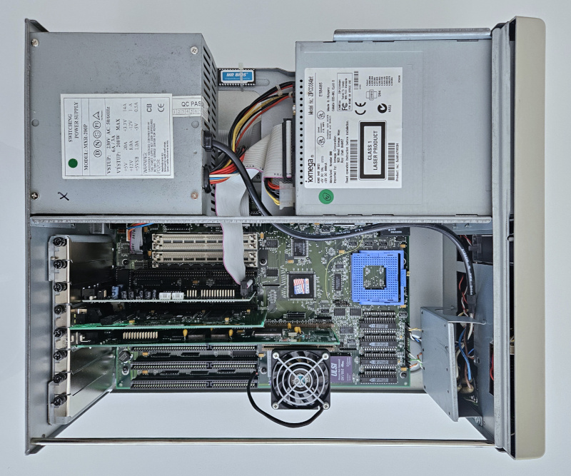
Anyway, I am certain that many of the Ambra and Aptiva machines with 4100 in the name had a BL3-100 as does my Patriot SL4100 so that numbering gets into 3rd party stuff with IBM microelectronics boards in. The surepath bios with CMOS wiped though, default boots them at 2x, so maybe 100s are missed, since first boot shows them at 66. Unless it's still in a machine with 100 badging you think you got a 66 that does 100 rather than a sold as 100. Anyway, while we might want to think of it as the best of the 386es, it was actually in the market as the worst of the 486es and sold to people who would not notice, at a time where none of them were very internet active and at a time where even if they were archive.org would preserve it poorly, and at a time where the support would blackhole completely due to not being WWW, and at a time where they would get scrapped if they had a millennium bug. In terms of survival traits, they had none, like an airbreathing fish that liked to eat fishing sinkers (weights).
There is also the probability that the 4100 models had a very short viable product lifespan, as a retail price SKU, 2 months, Patriot was dumping theirs through specials at office stores in late 94. The 466 came out a few months earlier and had that time to sell at retail. Everyone who knew anything by late 94 wanted a real Intel DX2-66 as bare minimum, a real DX4-100 if they could afford it, and with money to burn a Pentium, so these were on none of those people's radars. So when they didn't sell in 1994 due to intense competition and possibly better products being available at like, drug stores, they quite likely got debadged and shifted to discount warehouses. So what you're looking for in magazine ads are in the back cheaper listing pages "Famous name desktop 100mhz $299, free printer". Anyway, not unreleased, but released at such an inauspicious time, they made no ripples. Maybe there's a landfill full of them boxed and new, like that Atari game.
Edit: "Peak Ambra" or Ambra's last blast, ironically a September issue magazine when IBM killed Ambra in August of that year, illustrating the 2 month lead time lag common in magazines at the time. This is the "most ambra" mainstream PC publication I have ever found with several full page ads and reviews page 6 and 7 for instance for the BL systems. https://vintageapple.org/pcworld/pdf/PC_World … tember_1994.pdf Note that I should have said 4100BL as the 100-mhz BL3 indicator the convention 4100i in the model appears to indicate intel dx4. Nevertheless through carefully picking 16 bit only benchmarks Ambra tries to show the BL3 as keeping up with or better than intel. A different notebook review with a SLC2-66 noted it was beating a DX50 on some benches, so 16bit integer combined with the cache is keeping it "up there" on 16 bit DOS stuff.
Unicorn herding operations are proceeding, but all the totes of hens teeth and barrels of rocking horse poop give them plenty of hiding spots.


